-
Notifications
You must be signed in to change notification settings - Fork 48
2.2.2 Aquiring temperature
In STC-1000+ a temperature is represented by a 16-bit signed integer multiplied by 10. This is due to the fact that floating point numbers are to expensive to use and we want a resolution of 0.1°. So, for instance 34.7° will be stored as 347.
The sensor used is a negative temperature coefficient (NTC) thermistor (see 1.3 The temperature probe). That means it acts like a temperature dependent resistor, that as temperature rises exhibits less resistance. It is a 10k type, meaning is has a resistance of 10kOhm at room temperature (25 °C).

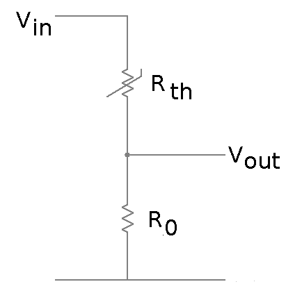
The thermistor is connected to an analog input on the MCU via voltage divider circuit (shown above). Vin is 5v, R0 is 10k and Vout is connected AN2 (analog input 2) on the MCU. The MCU has an analog-to-digital converter (ADC or A/D) connected to the analog inputs, that can sample the voltage on the pin and convert it to a digital value. The ADC in the PIC16F1828 has 10 bits of resolution, meaning it can convert the analog range (0 to 5 volts) into a digital value in the range 0 to 2^10-1 (that is 0-1023). This in turn means it can detect changes on the input signal in the order of 5/1024 volts (or about 5mV).
As an example, say the thermistor is at 25°C. That means it has the resistance 10kOhms. R0 also is 10kOhms, that means that Vout will be 5 * (10 / (10 + 10)) = 2.5v. The value read by the ADC will be 1023 * (10 / (10 + 10)) = 511. Say that the temperature changes and the resistance of the probe is now 20k. The value read by the ADC will then be 1023 * (10 / (10 + 20)) = 341.
The value read by the ADC is proportional to the resistance of the probe, and that is correlated to the temperature. It is however not a linear correlation, so we need to convert the value to a temperature in some way.
Due to the limitations of the MCU (no hardware for doing multiplications, divisions or floating point calculations) it is not feasible to try to calculate the temperature from the ADC value, so the method will be to use a look up table (LUT). Still, the ADC can provide 1024 different values. And as we need 16-bits to represent a temperature (it means that we need two instructions per value), the LUT would take up 2*1024 or 2K instructions! That is half of the available code space! That won't fly.

Now this is where we need to get crafty... We need to do this without using only integer calculations and no multiplications or divisions. We do have shifts though.
The 10-bit ADC value is split into two pieces. The upper 5 bits and the lower 5 bits. The upper 5 bits are more significant than the lower, and they are used as an index to the look up table. 5 bits means that the look up table will need hold 2^5 = 32 values (or 64 instructions, quite an improvement from 2048). So, the look up table will hold the temperature (multiplied by 10) as indicated by the most significant 5 bits of the ADC value. Now, this effectively turns our 10 bit ADC to a 5 bit ADC. We need to account for the lower 5 bits as well.
The lower 5 bits will say how far between the look up point of the upper 5 bits and the following look up point we are. To interpolate we loop 32 times (2^5) over a counter (from 0 to 31) and if the lower 5 bits of the ADC value is less or equal to the counter we add the first look up point to an accumulator, otherwise we add the following one. Once done, the accumulator will hold the temperature that is linearly interpolated between the look up points of interest, only 32 times too big as we have added 32 temperatures from the LUT. That is sorted by shifting the value down 5 steps.
The actual values for the look up table needs to be computed. The temperature-resistance relationship of the probe is known, but we need to calculate first the resistance at each of the look up points, and then the temperature for this resistance. This can be done manually (and initially I did), but that is error prone and and not very flexible. So, a LUT generator project was created. This will take the temperature-resistance data as input (as well as optional extra parameters such as R0 and how many data points we want for the LUT) and crunch the numbers automatically.
The ADC is fairly quick to convert the analogue voltage to a digital value and the process we want to regulate is slow. Another issue is that Fahrenheit scale has about twice the resolution of Celsius and as we move from the 'linear' part of the response curve from the probe, there isn't enough resolution to smoothly move between values. The solution is to sample temperature more often than needed and accumulate/average the values. This effectively gives us an 11 bit ADC (but a slower one).
The final piece of the puzzle to acquire a good temperature reading is filtering. Averaging is good, but we we can do better. Again given the limited resources, a 'cheap' solution is needed and that solution is the leaky integrator. Each sample is added to a 'pool' and then a fixed proportion of that pool is subtracted. With oversampling and filtering the sampled data, a nice, reliable (stable) and higher resolution temperature reading is produced, that can be used directly for regulation.
