SkyZone SteadyView Wiring
Before wiring up the RX to your SteadyView module, flash the RX of your choice with the firmware. Currently the firmware for SteadyView is in Pull Request #19
Change the setting in the goggles for the VRX type to "Thrid-Party", using the left jog wheel.
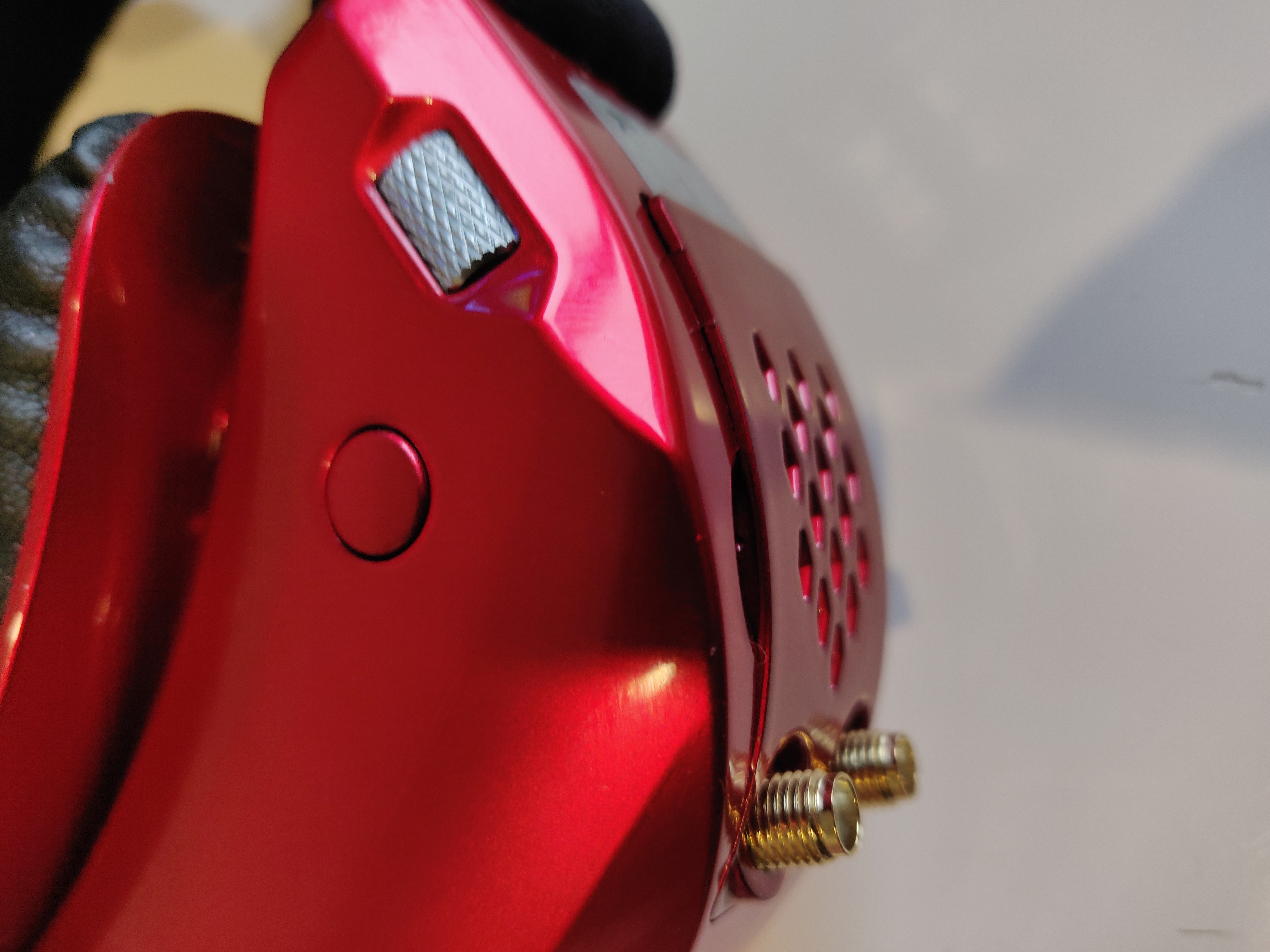
Wiring up the SkyZone SteadyView is a fairly simple process. It is however a semi-destructive process.
- Either desolder and pull pins 1-3 from the SteadyView, or cut them off, you may be able to just pull Pin 1.
- Wire as is shown in the image below
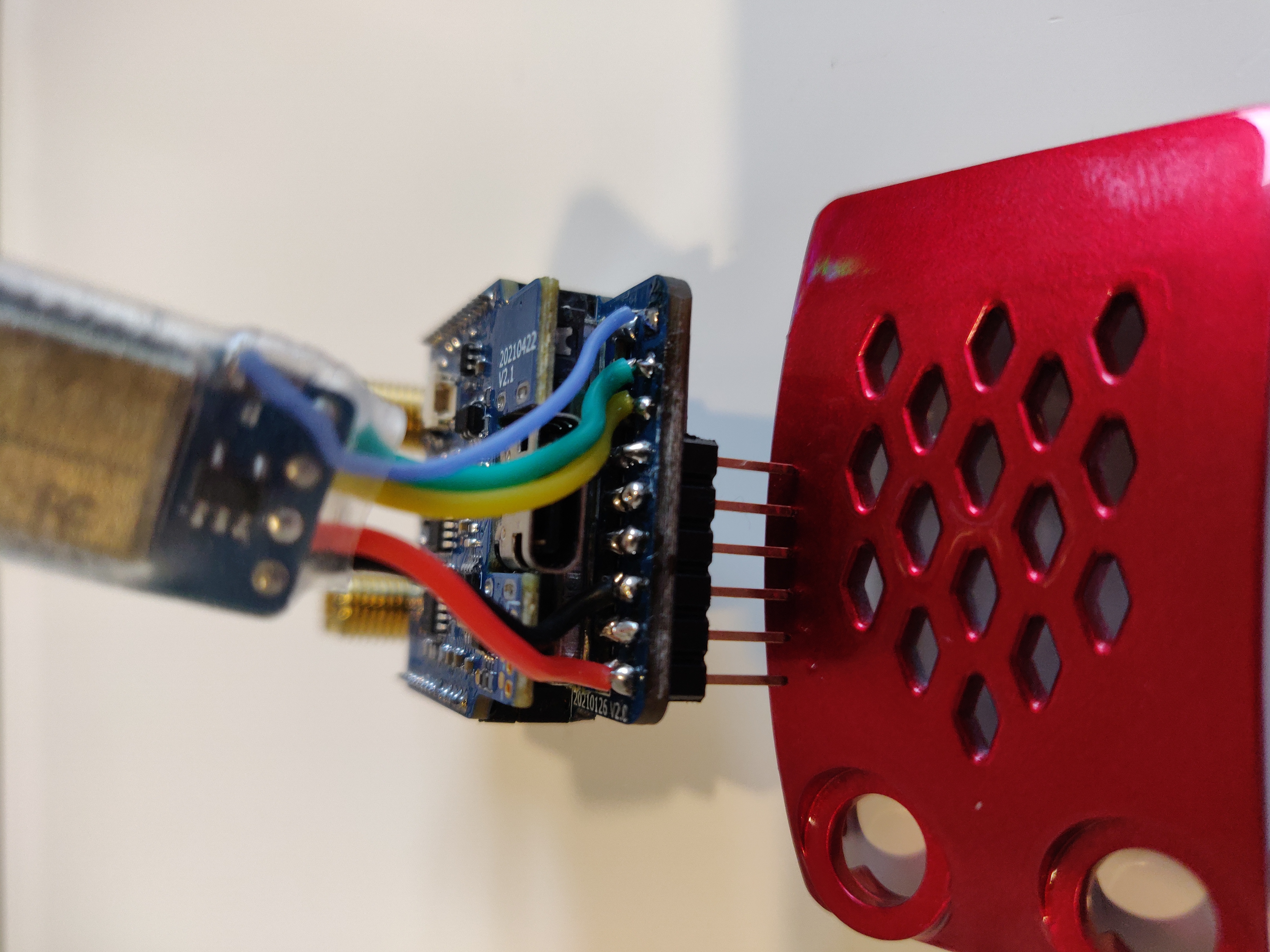
- The blue wire is connected to the boot-pad (make sure not to bridge to ground) and to pin 1 (CLK) of the Module Bay connector.
- The green wire is connected to the RX pad and to pin 2 (DATA) of the Module Bay connector.
- The Yellow wire is connected to the TX pad and to pin 3 (CS) of the Module Bay connector.
- The power wires are connected as follows.
- The black wire (GND) is connected to the 3rd pin from the end (Pin 7) of the Module Bay connector.
- The red wire (5V) is connected to the last pin (Pin 9) of the Module Bay connector.
- Once it's all wired up, insert the module back into the bay making sure the pins go into the module bay socket.
- Push the backpack RX into the space next to the module (there should be just enough room).
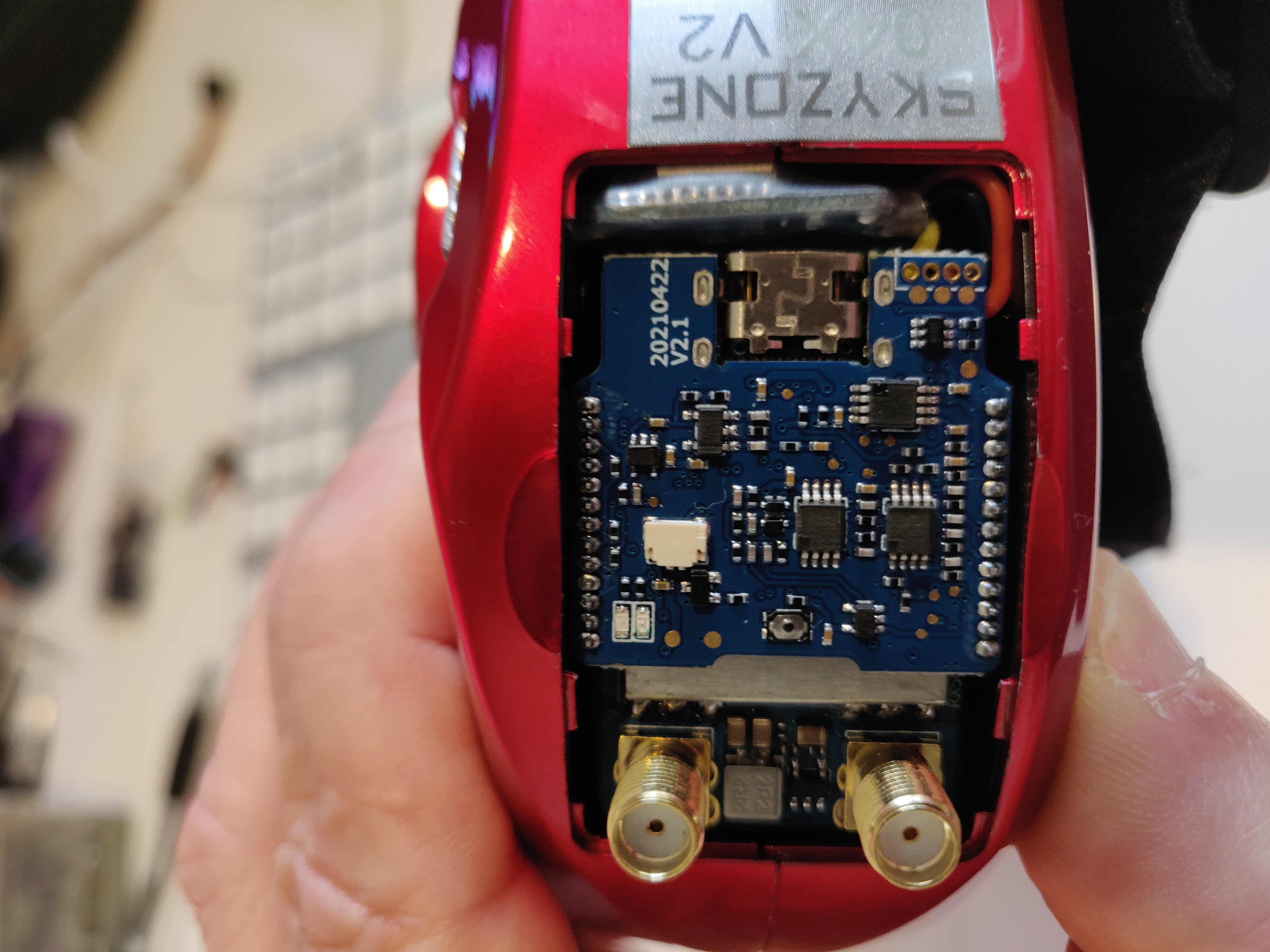
- Put the cover back on, with my RX it almost fits.