Teapotlabs BWLR1E is a solar-powered wireless LoRa environmental sensor capable of sensing temperature, humidity, air pressure and air quality using the on-board BME688. With STM32WLE MCU as it's core and AEM10941 for solar charging, the device is capable of multi-year operation with the possibility of indefinite battery-life by utilizing the solar charging capability
Teapotlabs BWLR1E is part of Teapot open-hardware project.
- The 1KM range is based on AERQ - Air Quality Monitoring design, but have not been tested on this device yet
The project won't be possible without the amazing work from people across the globe. The following are the reference to those awesome projects:
- RAK3172: An STM32WLE5CC module
- AEM10941: Solar energy harvesting
- 3.3V only power/pin.
- 3uA Deep-Sleep
- BME688 for Environmental Sensing
- Switchable TX Power. 14 dBm(50mA) or 22 dBm(140mA) ( on 915MHz frequency )
- Supports LoRaWAN 1.0.3
- 1KM+ Range
- UART2 breakout for Arduino/Mbed OS/STM32Cube programming
- SWD breakout for debugging and programming
- iPEX antenna connector
- 3.7 Volts LiPo Battery
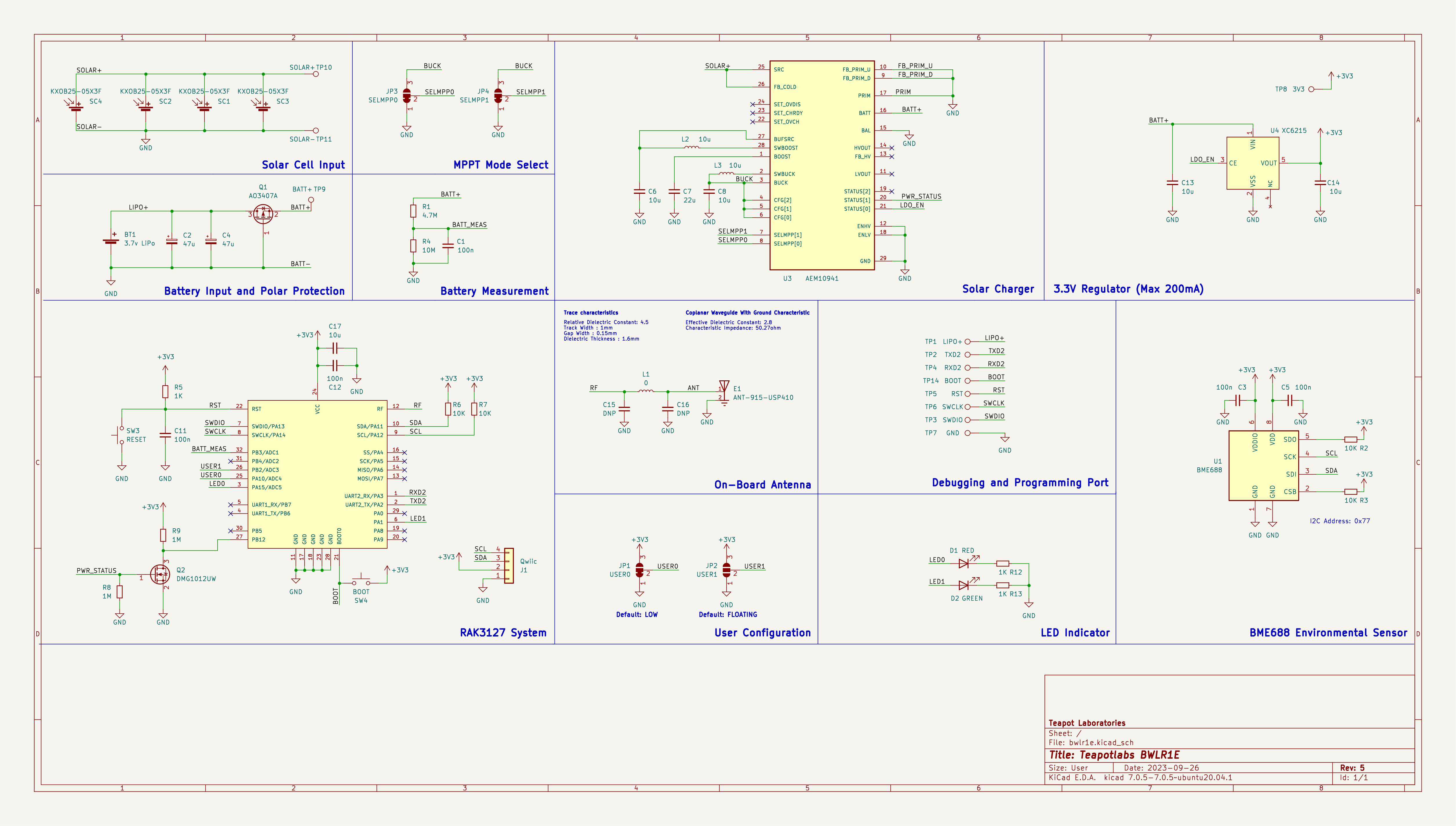

PCB Render
Built using KiCAD, the board is design to be as small as possible with all components placed on the top side of the PCB. The following are the lists of revision of the board:
- Revision 1: Initial design
- Revision 2: Better trace, use rounded trace and change solar cell wiring to parallel for all cell
- Revision 3: Rename 3V3 to PRIMIN and breaks out PRIMIN
- Revision 4: Improve layout and wiring, and add Qwiic connector
- Revision 5: Change C6 to 22uF
The following design are based on the latest revision.
| Top Board | Bottom Board |
|---|---|
|
|
|
|


PCB Top and Bottom Layout

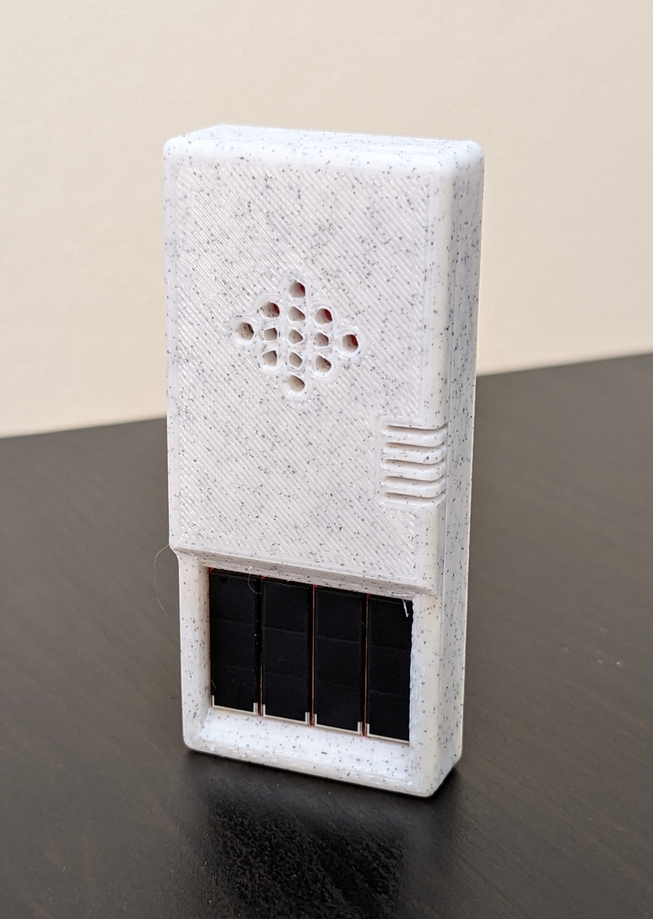
Built using TinkerCAD. The case are 3D printable with any generic 3D printer with/without support. The STL files are available here

Case Open
For adding additional sensors, Qwiic connector is also available on the left side of the board.

Connecting to Adafruit BME688
The case is design to be as small as possible with an additional magnets in the back to ease the placement of the sensor. The following are the list of material used at the time of testing:
- 3.7v LiPo Battery, 850mAh 6mm x 30mm x 48mm
- 4 piece of 8mm x 2mm neodymium magnet

Sensor Placement with Magnet
Power consumption and solar charging current are measured using Nordic PPK2 and CurrentRanger. The following are the summary of the measurement:
- Transmit 14dBm: 305ms @ 20mA
- Deep-Sleep : 3.22 uA
- Direct Sunlight Solar Charge: 9mA
- Indirect Sunlight Solar Charge: 300uA
⚠️ Tested on Revision 3, but should be similar to Revision 5

Deep-Sleep

BME688 Measure and LoRa Transmit
| Solar Charge - Direct Sunlight | Solar Charge - Indirect Sunlight |
|---|---|
|
|


More measurement can be found here
Most of the components are generic and can be bought from any electornics/semi-conductor distributor. RAK3172 is the only component available in RAKwireless store. The bill of materials can be downloaded here
⚠️ Be sure to buy the RAK3172 variant without IPEX to use the On-Board Antenna
⚠️ Board can only be powered when LiPo battery is connected
Programming the device can be done over the UART2 or SWD, available on the right side of the board or uses the BWLR1E Programmer. Out of the factory, the RAK3172 chip ships with an AT firmware that can be tested by connecting a USB-to-UART bridge to the UART2 port.
The following are some very good tutorial to start developing with the device:
- Communicating with the AT firmware
- Programming with Arduino
- Programming with STM32Cube
- Programming with MbedOS
For connecting to the UART2 port, use any USB-to-UART bridge module. In testing, the Sparkfun board is used for communication with AT firmware and programming over Arduino.
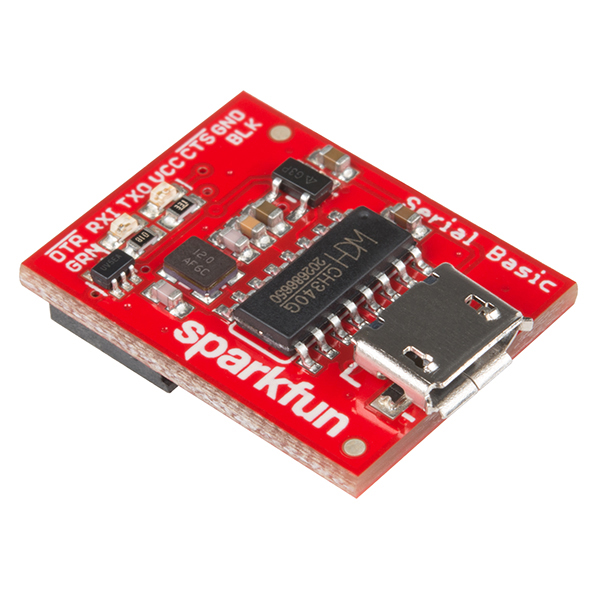
Sparkfun USB-to-UART Bridge
⚠️ Be sure to only use 3.3V module. Do not 5V module
Through UART2, user can program the device using the following SDK:
Other than Arduino RUI3 SDK, to program the device, user need to put the device in Serial Bootloader mode by,
- Press and Hold
BOOTandRESETbutton - Release
RESETbutton - Wait few seconds ( try 2 seconds )
- Release
BOOTbutton - Device should be in Serial Bootloader mode.
You can also use STM32CubeProgrammer , instead of the SDK to upload a firmware
Teapotlabs BWLR1E Programmer
An alternative to solder-free programming is to use the Teapotlabs BWLR1E Programmer. A full detail of the device can be found here. The programmer connects to UART2 of the device.
The product is open-source! However, some part of library used under src, might have it's own license. Please reach out or create a ticket to report any license violation.