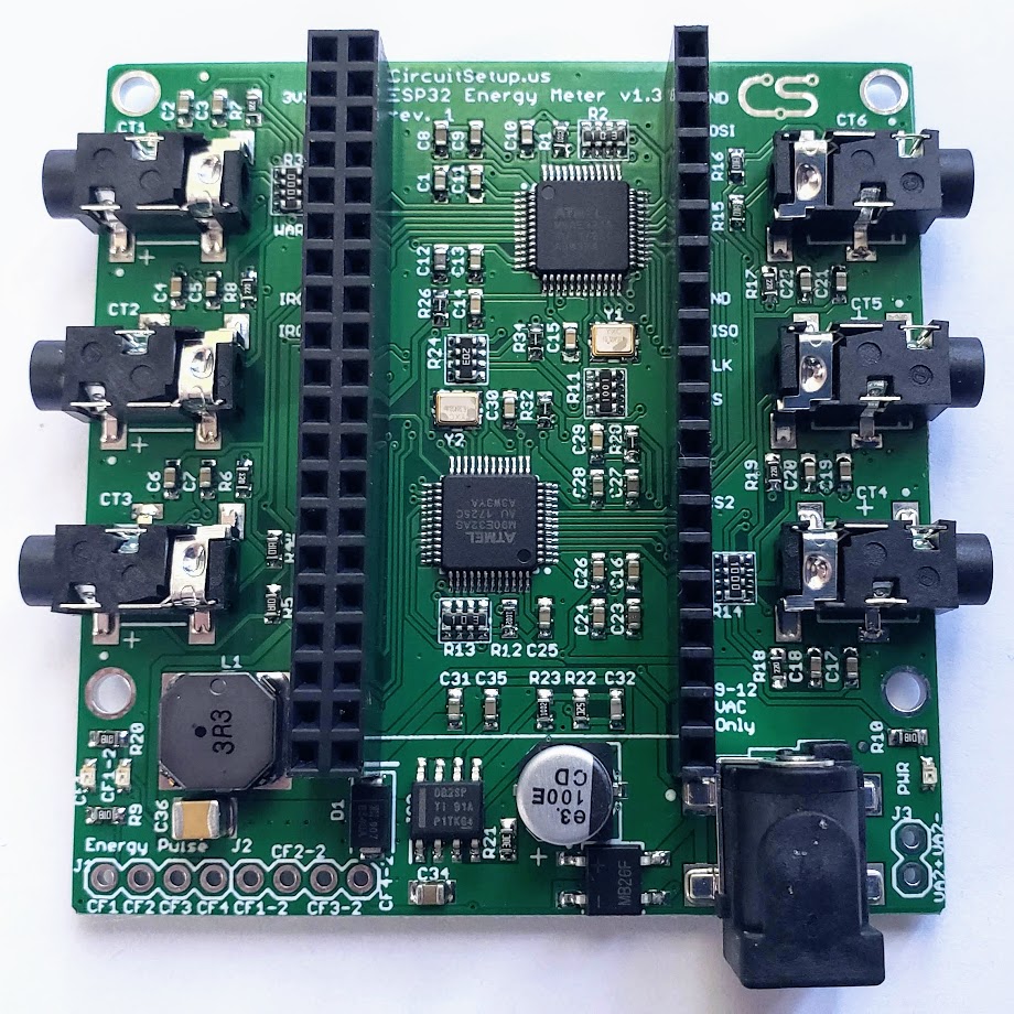
The Expandable 6 Channel ESP32 Energy Meter can read 6 current channels and 2 voltage channels at a time. Much like our Split Single Phase Energy Meter, the 6 channel uses current transformers and an AC transformer to measure voltage and power the board(s)/ESP32. The main board includes a buck converter to power the electronics and ESP32 dev board, which plugs directly into the board. Up to 6 add-on boards can stack on top of the main board to allow you to monitor up to 42 current channels in 16-bit resolution, in real time, all at once! This product is currently in the prototype stage, so components may change.
- Samples 6 current channels & 1 voltage channel (expandable to 2 voltage)
- Add-on boards (up to 6) can expand the meter up to 42 current channels & 8 voltage channels
- Uses 2 Microchip ATM90E32AS - 3 current channels & 1 voltage per IC
- For each channel the following can also be calculated by the meter:
- Active Power
- Reactive Power
- Apparent Power
- Power Factor
- Frequency
- Temperature
- Uses standard current transformer clamps to sample current
- 22ohm burden resistors per current channel
- Includes built-in buck converter to power ESP32 & electronics
- 2 IRQ interrupts, and 1 Warning outputs
- Zero crossing outputs
- Energy Pulse outputs per IC (4 per IC x2)
- SPI Interface
- Measurement Error: 0.1%
- Dynamic Range: 6000:1
- Gain Selection: Up to 4x
- Voltage Reference Drift Typical (ppm/°C): 6
- ADC Resolution (bits): 16
- Current Transformers (depending on your application)
- SCT-013-030 30A/1V
- SCT-013-050 50A/1V
- SCT-013-000 100A/50mA (13mm opening - 3.5mm connectors)
- SCT-016 120A/40mA (16mm opening - 3.5mm connectors)
- Magnelab SCT-0750-100 (screw connectors - must sever burden resistor connection on the back of the board since they have a built in burden resistor).
- Others can also be used as long as they're rated for the amount of power that you are wanting to measure, and have a current output no more than 720mA.
- AC Transformer: Jameco Reliapro 9v or 12v. The positive pin must be 2.5mm (some are 2.1)
- ESP32 (choose one):
- NodeMCU
- Espressif DevKitC
- DevKitC-32U if you need better wifi reception (don't forget the antenna)
- Anything else with the same pinouts as the above, which are usually 19 pins per side with 3v3 in the upper left & CLK in the lower right
- Software (choose one):
- Our custom version of EmonESP and the ATM90E32 Arduino library
- The current dev release of ESPHome. Details on integration with Home Assistant are located here. and here on ESPHome.io
- Libraries for CircuitPython & MicroPython
The Expandable 6 Channel ESP32 Energy Meter is made so that an ESP32 dev board can be plugged directly into the meter. See the list above for compatible ESP32 dev boards. Always inset the ESP32 with the 3V3 pin in the upper left of the meter. The bottom pins are used to connect the voltage signal (from the power plug) to add-on boards. If the ESP32 is inserted into the bottom pins it will more than likely short the ESP32.
The Expandable 6 Channel ESP32 Energy Meter uses SPI to communicate with the ESP32. Each board uses 2 CS pins.
The main board uses the following SPI pins:
- CLK - 18
- MISO - 19
- MOSI - 23
- CS1 - 5 (CT1-CT3 & Voltage 1)
- CS2 - 4 (CT4-CT6 & Voltage 2)
The add-on board allows the CS pin to be selected based on the jumper settings at the bottom of the board. This is so multiple add-on boards can be used - up to 6 maximum. Do NOT select more than one CS pin per bank. The CS pins can be:
- CT1-CT3 (CS):
- For v1.3 and under:
- 0
- 2 (*make sure that an on board LED is not used for IO2 on the ESP32)
- 12 (*will cause ESP32 to not boot if used)
- 13
- 14
- 15
- For v1.4 and above:
- 0
- 27
- 35
- 13
- 14
- 15
- For v1.3 and under:
- CT4-CT6 (CS2):
- 16
- 17
- 21
- 22
- 25
- 26
The Expandable 6 Channel ESP32 Energy Meter uses 2 ATM90E32AS ICs. Each IC has 3 voltage channels and 3 current channels. In order for power metering data to be calculated internally, each current channel must have a reference voltage. If the voltage is out of phase with the current, then the current and power will read as negative.
v1.1 of the meter used 1 of the voltage channels for each IC. This means that power and metering data would have to be calculated in software, or volage channels would have to be mapped via changing registers on the IC to get power and metering data from CT2, CT3, CT5, CT6.
v1.2 & v1.3 have JP8-JP11 on the back of the board, that would allow all voltage channels to be connected together, which would allow power and other metering values to be calculated. Most of v1.3 came soldered together.
v1.4 removed JP8-JP11, and has voltage channels connected internally on the pcb.
The holes labeled VA2 next to the power plug on the meter main board, and in the bottom right of the add-on board are for measuring a second voltage. To do this you must:
- Sever (with a knife) JP12 and JP13 on the back of the board for v1.3+, or JP7 for prior versions
- Use a second AC transformer, ideally one idential to the primary
- Plug in the second AC transformer to an outlet on the opposite phase to the primary
- Solder on a pin header, 2.54mm screw connector, or pigtail on to VA2+ & VA2-
When voltage jumpers are severed, the voltage reference for CT4-CT6 will be from VA2. This means that current transformers for CT4-CT6 should be hooked up to circuits that are on the same phase as VA2, and CT1-CT3 should be hooked up to circuits are are in phase with the primary voltage. If a CT is not in phase with the voltage its current and power readings will be negative. If, for example, you have 4 circuits in phase with the primary, and 2 in phase with VA2, you can reverse the current transformer on the wire to put it in phase with the voltage.
For add-on boards, the primary voltage will come from the main board. The optional secondary voltage measurement (also VA2 pins), will be in phase with CT4-CT6.