This repository includes all the files used in the mtt YouTube video, "Apple's BEST keyboard... reimagined".
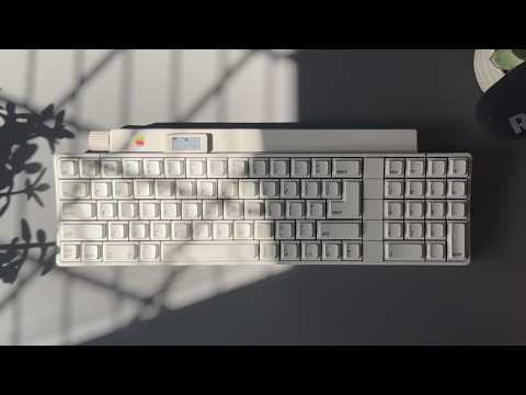
The 1986 Apple Desktop Bus Keyboard is a design marvel known for its enjoyable typing experience, but using it today requires some engineering. This modernization project introduces a custom PCB and development board to add Bluetooth connectivity using ZMK, a low-energy display for layer and device status, and a rotary encoder for volume control.
This README can be used as supporting information to the video. If you are undertaking this project yourself, please familiarize yourself with ZMK firmware, and the PCB design and schematic files.
The results will vary depending on the condition of your keyboard.
While efforts have been made to create a functional project, variations in individual keyboard conditions may lead to unique issues.
The PCB was designed in KiCad 8.0.
The Schematic, Design, and component Footprints are included in the KiCad project files.
If you are working on this project, take the time to thoroughly review the design and schematic to understand PCB utilization.
| Description | Part | Quantity | Link |
|---|---|---|---|
| Development Board | Seeed Studio XIAO nRF52840 | 1 | Seeed Studio |
| Display | nice!view | 1 | nice! |
| Rotary encoder | EC11 | 1 | Amazon |
| USB Port | USB TYPE-C 6P | 1 | LCSC Electronics |
| Display/Encoder receptacle | JST SM05B | 2 | LCSC Electronics |
| Display/Encoder plug | JST SHR-05V-S-B | 2 | See below |
| Lithium Polymer Battery | 110mAh | 1 | Cool Components |
| Battery Connector | JST S2B-PH | 1 | LCSC Electronics |
| 10k resistor | 10k 0805 | 4 | LCSC Electronics |
| 5.1k resistor | 5.1k 0805 | 2 | LCSC Electronics |
| Power switch | MINI MSK12CO2 | 1 | LCSC Electronics |
As the small JST connectors used to connect the PCB to the display and rotary encoder requires specialist crimping tools, I opted to have the two cables fabricated by LCSC custom cables, to the following specification:
| LCSC Part | Manufacture Part | Quantity |
|---|---|---|
| C268102 | JST SHR-05V-S-B | 1 |
| C263995 | SSH-003T-P0.2-H | 5 |
- Cable: AWG 30
- Length: 300mm
- Side 1: JST Connector
- Side 2: Flat cut wires
For convenience, the Production files have been included in this repository. These can be used to order your own PCB from a prototyping company, such as JLCPCB or PCBWay.
Please be comfortable with the ordering and validation process, as each company is different and may have inaccuracies you are responsible for.
- Upload the ./assets/pcb/production-packed.zip to a provider.
- If using the Assembly services, make sure all components are correctly placed.
If you want to modify the firmware, you can review the code in ./boards/shields/adbk following the guidance from ZMK documentation.
I have added a release with the firmware I use daily.
- Connect the XIAO to your computer.
- Download the adbk_fw.uf2 from the Releases.
- Place the XIAO nRF52840 in bootloader mode.
- Drag and drop the adbk_fw.uf2 file to the XIAO-SENSE volume on your computer.
The board will automatically exit bootloader mode and is ready to use.
If you have ordered from a fabrication company with assembly services, the may only have to solder the XIAO nRF52840 and through-hole component.
Review the schematic and design files to understand how the components are placed on the PCB.
To install the custom components, some parts need to be removed. The process is reversible, allowing the keyboard to be restored to its original state.
- Flip over the keyboard and remove the 3x screws with a PH2 driver bit.
- Holding the top of the keyboard, return it to the upright position, then remove the top casing by lifting it upwards.
- Carefully remove the 20 pin DIP package by lifting each side with equal force.
- Remove the board from the PCB, by lift the top, and then sliding it upwards.
- Desolder and remove the ADB ports.
- Store the ADB ports and 20-pin DIP package in anti-static packaging for preservation.
The following parts help facilitate the modifications. These are:
- Power button with Display cutout
- ADB Port with switch and USB-C cutout
- ADB Port with EC11 cutout
- EC11 encoder knob
These files are provided in STEP and 3MF formats.
STEP allows for accurate modification in CAD software.
3MF is designed to be more accessible for 3D printing.