This is a libgpiod2 rewrite of https://github.com/thecode/ha-rpi_gpio to support generic GPIO devices.
This integration supports any device with libgpiod 2.0.2 or later, i.e. all versions of Raspberry Pi,
including Raspberry Pi 5. The platform will guess sensible defaults for the GPIO device path,
or you can use device when defining entities to select the GPIO device (e.g. /dev/gpiochip4).
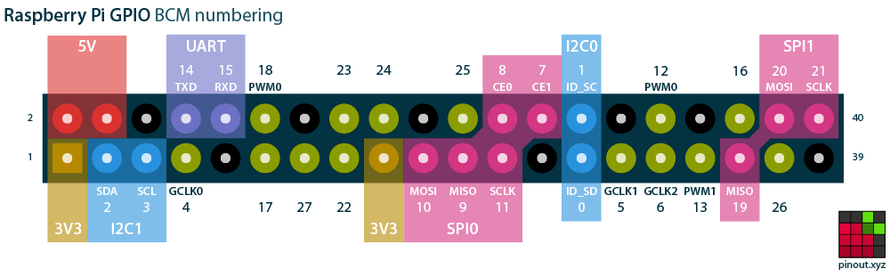
Note that port referrs to the GPIO number, not the pin number. This can be unintuitive on some
platforms. For example, if you have a relay connected to pin 11 of the Raspberry Pi, its GPIO number
is 17. See the Wikipedia article about the Raspberry Pi for more details about the GPIO layout.
The gpio integration supports the following platforms: Binary Sensor, Cover, and Switch.
As soon as this PR is accepted, the recommend way to install gpio will be through HACS.
Copy the gpio folder and all of its contents into your Home Assistant's
custom_components folder. This folder is usually inside your /config
folder. If you are running Hass.io, use SAMBA to copy the folder over. You
may need to create the custom_components folder and then copy the gpio
folder and all of its contents into it.
The gpio binary sensor platform allows you to read sensor values of the GPIOs of your device.
Legacy binary sensor configuration
Add the following to your configuration.yaml file:
# Basic configuration.yaml entry
binary_sensor:
  - platform: gpio
    sensors:
      - port: 11
        name: "PIR Office"
      - port: 12
        name: "PIR Bedroom"
# Full configuration.yaml entry
binary_sensor:
- platform: gpio
sensors:
- port: 11
device: "/dev/gpiochip4"
name: "PIR Office"
unique_id: "pir_office_sensor_port_11"
bouncetime: 80
invert_logic: true
pull_mode: "DOWN"| Key | Required | Default | Type | Description |
|---|---|---|---|---|
sensors |
yes | list | List of sensor IO ports (BCM mode pin numbers) | |
port |
yes | integer | The GPIO port (a.k.a line) number | |
name |
yes | string | The name for the binary sensor entity | |
device |
no | Hardware dependent | string | Path to the GPIO device, e.g. /dev/gpiochip4 |
unique_id |
no | string | An ID that uniquely identifies the sensor. Set this to a unique value to allow customization through the UI | |
bouncetime |
no | 50 |
integer | The time in milliseconds for port debouncing |
invert_logic |
no | false (ACTIVE HIGH) |
boolean | If true, inverts the output logic to ACTIVE LOW |
pull_mode |
no | UP |
string | Type of internal pull resistor to use: UP - pull-up resistor, DOWN - pull-down resistor |
The gpio cover platform allows you to use a GPIO device to control covers, e.g. a garage door.
It uses two pins on the GPIO device:
- The
state_pinwill detect if the cover is closed, and - the
relay_pinwill trigger the cover to open or close.
Although you do not need Andrews Hilliday's software controller when you run Home Assistant, he has written clear instructions on how to hook your garage door and sensors up to your Raspberry Pi, which can be found here.
Add the following to your configuration.yaml file:
# Basic configuration.yaml entry
cover:
  - platform: gpio
    covers:
      - relay_pin: 10
        state_pin: 11
# Full configuration.yaml entry
cover:
- platform: gpio
relay_time: 0.2
invert_relay: false
state_pull_mode: "UP"
invert_state: true
covers:
- relay_pin: 12
state_pin: 13
device: "/dev/gpiochip4"
name: "Right door"
unique_id: "right_door_cover_port_13"| Key | Required | Default | Type | Description |
|---|---|---|---|---|
relay_time |
no | 0.2 |
float | The time that the relay will be on for in seconds |
invert_relay |
no | false |
boolean | Invert the relay pin output so that it is active-high (True) |
state_pull_mode |
no | UP |
string | The direction the State pin is pulling. It can be UP or DOWN |
invert_state |
no | false |
boolean | Invert the value of the State pin so that 0 means closed |
covers |
yes | list | List of covers | |
relay_pin |
yes | integer | The pin of your Raspberry Pi where the relay is connected | |
state_pin |
yes | integer | The pin of your Raspberry Pi to retrieve the state | |
device |
no | Hardware dependent | string | Path to the GPIO device, e.g. /dev/gpiochip4 |
name |
no | string | The name for the cover entity | |
unique_id |
no | string | An ID that uniquely identifies the cover. Set this to a unique value to allow customization through the UI |
The gpio switch platform allows you to control the GPIOs of your device.
Add the following to your configuration.yaml file:
# Basic configuration.yaml entry
switch:
  - platform: gpio
    switches:
      - port: 11
        name: "Fan Office"
      - port: 12
        name: "Light Desk"
# Full configuration.yaml entry
switch:
- platform: gpio
switches:
- port: 11
device: "/dev/gpiochip4"
name: "Fan Office"
unique_id: "fan_office_switch_port_11"
invert_logic: true| Key | Required | Default | Type | Description |
|---|---|---|---|---|
switches |
yes | list | List of switch IO ports (BCM mode pin numbers) | |
name |
yes | string | The name for the switch entity | |
device |
no | Hardware dependent | string | Path to the GPIO device, e.g. /dev/gpiochip4 |
unique_id |
no | string | An ID that uniquely identifies the switch. Set this to a unique value to allow customization through the UI | |
invert_logic |
no | false |
boolean | If true, inverts the output logic to ACTIVE LOW |