This project aims at making a portable wireless timing system that's primary use is for athletics. The project's main sport of focus to start is alpine ski racing.
In alpine ski racing a racer starts at the top of a race and goes through a wand which starts their time and the finish is triggered when the race crosses the "eyes" at the bottom. Finish eyes traditionally use some form of LASER or light break beam. During training sessions some teams will use wireless timing systems which can do this task with no wired set up required. This is a great training tool as it can tell you who is going fastest and when people are improving, and most teams who have them are able to see more improvements. One issue with current systems is they are expensive, some of them are outdated and haven't been upgraded in decades, and many of them are not very user friendly. That’s why this project was born! The goal is to use Arduino's and Raspberry Pi's to create a wireless timer which is cheaper and aims at usability.
- Wireless Timing via LoRa line of site up to 20km
- Start and Finish currently, plans to support monitor tablet and multiple intervals
- Pace Mode and Stopwatch Mode
- Finish line length of up to 40m
- Virtually unlimited number of people on the track at one time
- Virtually unlimited space for runs
- Resistive touch screen to be able to provide a user-friendly UI while still allowing use of gloves or hand protection
Below is a link to a YouTube video demonstrating simple usage and proof of work for the idea:
- How to solder
- Basic C/C++ programming knowledge would be an asset (e.g. loops, constants)
- Basic Knowledge of Linux systems (e.g. file system, terminal use)
- How to upload Arduino libraries
- How to import new Arduino libraries
The idea behind the hardware set up is that the Arduino is used for sensors for the outside world while the Raspberry Pi (RPi) is responsible for handling the display as well as doing the information processing and storing information.
- Raspberry Pi Zero W (https://www.raspberrypi.org/products/raspberry-pi-zero-w/)
- Arduino UNO (https://store.arduino.cc/usa/arduino-uno-rev3)
- Waveshare 4inch HDMI LCD, 800×480, IPS (https://www.waveshare.com/4inch-HDMI-LCD.htm)
- Adafruit RFM95W LoRa Radio Transceiver Breakout - 868 or 915 MHz (https://www.adafruit.com/product/3072)
- 4-channel I2C-safe Bi-directional Logic Level Converter (https://www.adafruit.com/product/757)
- MCP3008 - 8-Channel 10-Bit ADC With SPI Interface (https://www.adafruit.com/product/856)
- PowerBoost 1000 Charger - Rechargeable 5V Lipo USB Boost @ 1A - 1000C (https://www.adafruit.com/product/2465)
- Lithium Ion Battery Pack - 3.7V 6600mAh (https://www.adafruit.com/product/353)
- MicroSD Card
- 100k resistor
- Momentary push button
- Yellow LED
- Red LED
- Blue LED
- 4 x 10k resistor
- 3 x 4001N diode
- 3 x 330 Ohm resistor
- 2 x 6.8k resistor
- LIDAR-Lite v3 (https://www.sparkfun.com/products/14032)
- Magnetic contact switch (https://www.adafruit.com/product/375)
If you look in the diagrams folder you will find fritzing diagrams of how the different pieces need to be set up. The RPi and Arduino are connected through two different connections, the serial pins (UART) and I2C.
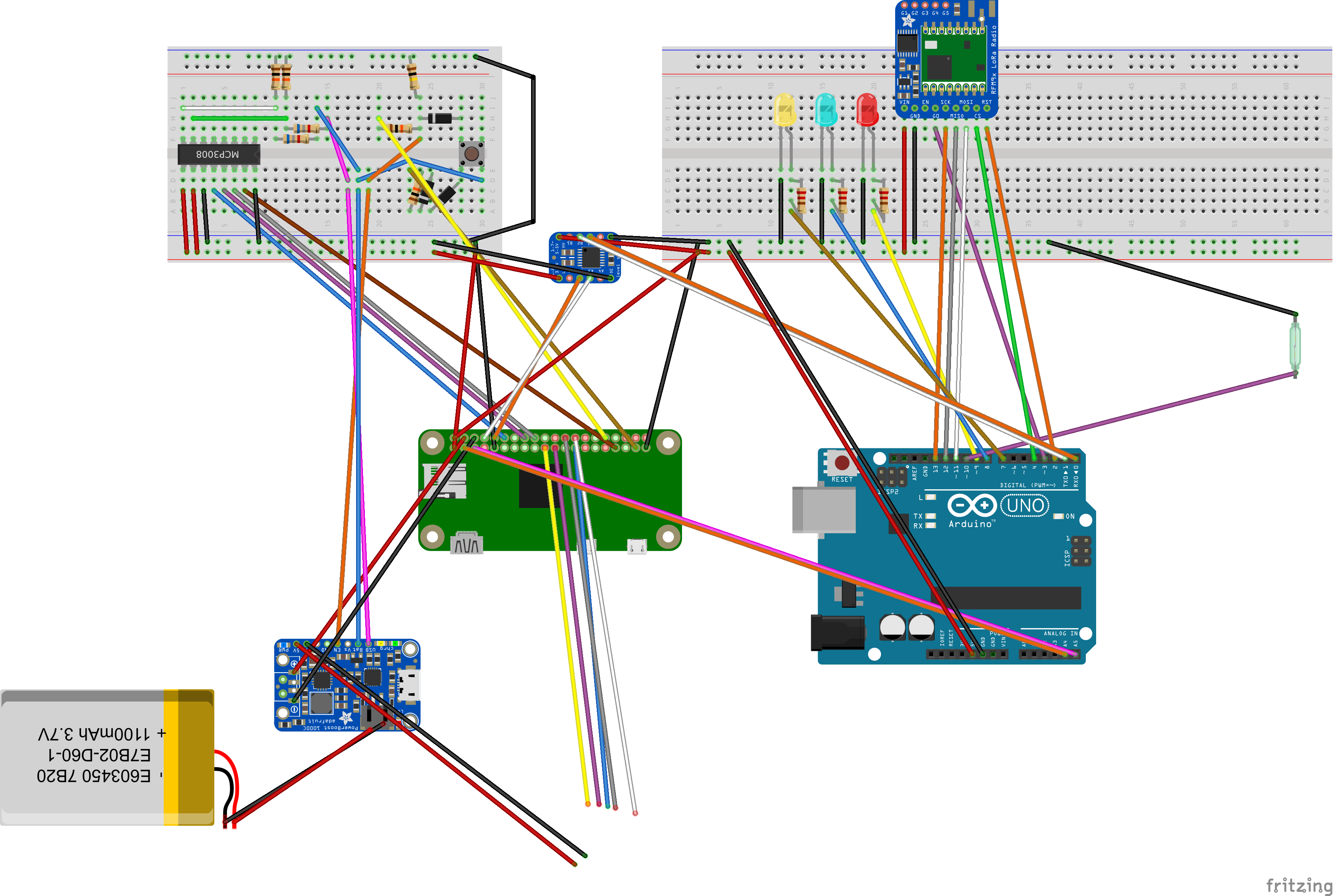
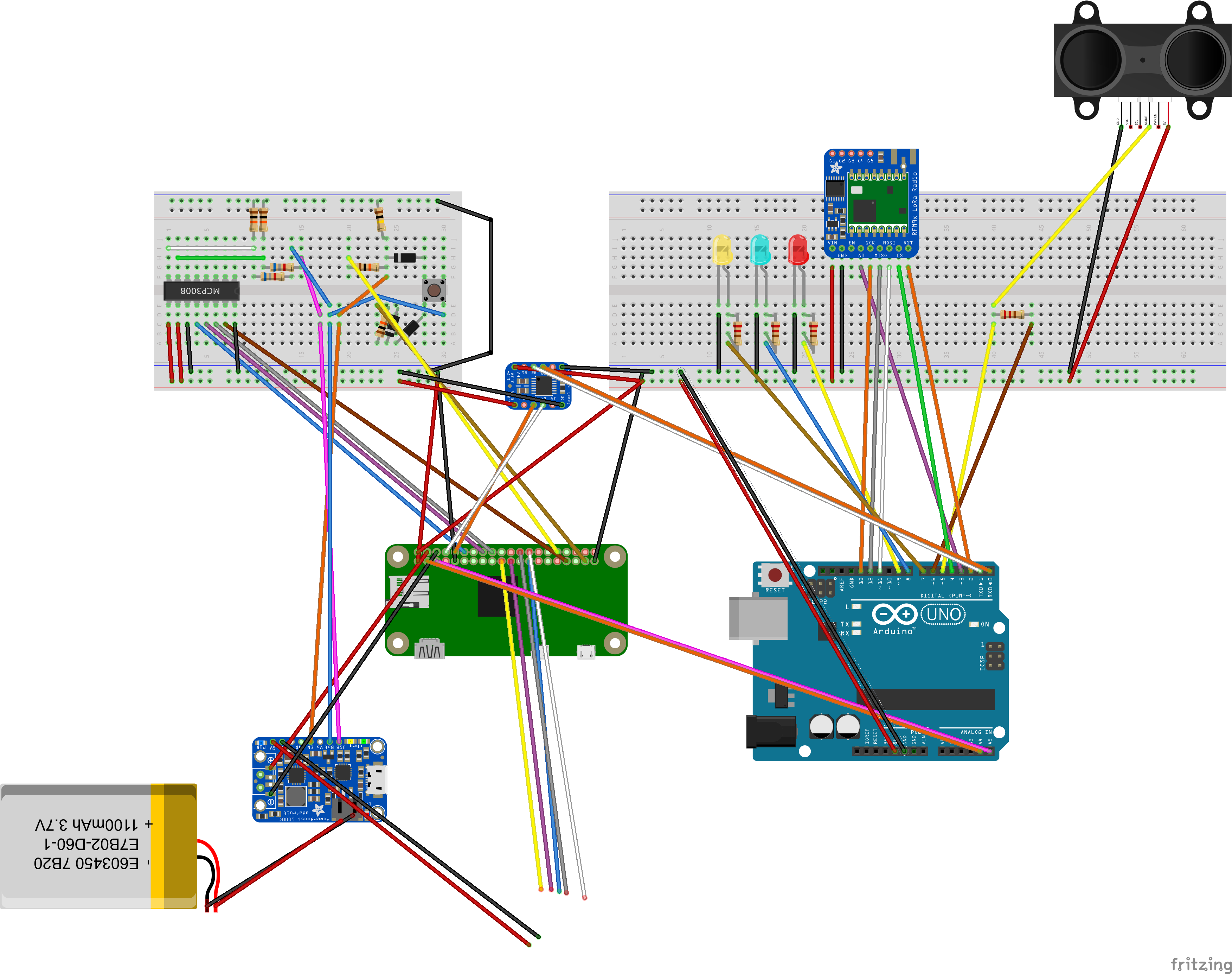
- Where the wires disappear in the diagram is where they connect to a Waveshare 4" resistive touchscreen LCD
- In my set, up I used a 6600 mAH battery
- Yellow LED is the TX LED for the Arduino
- Blue LED is the RX LED for the Arduino
- Red LED is the error LED for the Arduino
- The LCD get's its own 5V power supply from the PowerBoost because it draws a large current and when it get's it's power from the rail on the breadboard I observed some flickering
All of them are required to run the WirelessTimer software, however for pi_power it is suggested that you use the script provided in this repository as it has been modified to accommodate the different battery voltage and different pins used.
- WirelessTimer: https://github.com/ianmott77/wireless-timer-rpi
- pi_power (modified): https://github.com/ianmott77/wireless-timer/blob/master/pi_power.py (Big thanks to @craic!! Original repo found here https://github.com/craic/pi_power)
- WirelessTimer: https://github.com/ianmott77/wireless-timer-arduino
- RadioHead: http://www.airspayce.com/mikem/arduino/RadioHead/
- LIDARLite V3: https://github.com/garmin/LIDARLite_v3_Arduino_Library
To set up the software for the Arduino start by downloading the WirelessTimer repo. The CLI folder contains the main program for the Arduino while the Connection folder contains the framework that it's built on. To install the program, add the Connection library, the RadioHead library and the LIDARLite V3 library to the Arduino software (instruction here: https://www.arduino.cc/en/hacking/libraries).
Inside the repo you will also find a folder named "tools" inside this folder you will find a script name "WriteDeviceID" in order to set up the Arduino we need to write a Device ID to it's EEPROM which will be saved permanently and should be unique for all the timers in your network. If you open the script you will find a script like this
#include <EEPROM.h>
#define DEVICE_ID x

void setup(){
    EEPROM.write(0, DEVICE_ID);
}
void loop(){}
To write your desired unique device ID to the Arduino simply change where the "x" is to the unique device ID number you want and upload it to the Arduino. The device ID will be save permanently to the Arduino, after you run this script once you won't have to run it on an Arduino again unless you are changing its device type.
Inside the repo you will also find a folder named "tools" inside this folder you will find a script name "WriteDeviceType" in order to set up the Arduino we need to write the device type to the Arduino. There are 3 different device types
- 1 = Starter
- 2 = Interval (Finish Eyes)
- 3 = Monitor Node (not yet implemented)
#include <EEPROM.h>
#define DEVICE_TYPE x

void setup(){
    EEPROM.write(1, DEVICE_TYPE);
}
void loop(){}
To set the device type of the Arduino simply change the "x" in the script to the device type of you need and upload it to the Arduino. The device type will be save permanently to the Arduino, after you run this script once you won't have to run it on an Arduino again unless you are changing its device ID.
The final set up step for an Arduino is to upload the CLI script. Once you have done that the setup is complete. If everything is wired correctly you should see all three lights blink once, and nothing should be displayed on the serial monitor in the Arduino IDE if you have that open.
This project uses Raspbian Stretch Lite (https://www.raspberrypi.org/downloads/raspbian/) as it's base but requires several steps to set up. In future this will all be rolled in to a custom image but currently requires manual set up.
To set up the Wireless timer software you first need to write the Raspbian Lite image to a micro SD card which is compatible with Raspberry Pi Zero W's (most micro SD's should work). If you're not sure how to do this, you can find detailed instructions here:
To login the default username for the OS is "pi" and the default password is "raspberry"
The Waveshare screen should work with and HDMI connection from the RPi by default however the display may be the wrong orientation and it may be the wrong resolution, and the touch functionality won't work properly. You can follow the instructions found here:
to setup the display properly. Once the drivers are installed you can test weather or not it is working with the program evtest. evtest is used to test input. It can be installed by typingsudo apt-get install evtest and it can be run by typing evtest. If you are not getting any input when touching the screen, check the connection and that you have the screen connected to the proper pins on the RPi.
To set up pi power you can follow the instructions here however read bellow for the modifications made for this project:
however, the script hosted in this repository is set up to use GPIO12 for boot up and GPIO13 to replace GPIO25, because GPIO25 is used by the touch screen, and the max and minimum voltages are adjusted for the battery I used.
In pi_power GPIO14 is used to power up the RPi because it goes high when booting up but goes low when powering down, however GPIO14 is the TX pin for the RPi and used by the Arduino to communicate. To accommodate this, we simulate GPIO12 going high when booting by using a custom device tree blob, detailed instructions on how to set this up can be found here:
to simulate GPIO12 going high when the RPi boot's we set it to output mode, and active. I have provided a dt-blob.dts in this repo which does that and should allow GPIO12 to be high after holding the momentary push button for a couple second and will go low when the RPi shuts down.
Currently the only way to use this project is to build the WirelessTimer from scratch and currently the only host system tested so far is Ubuntu 17.10.
The Raspberry Pi portion of the project is based on QT. You can download QT for free here:
For the WirelessTimer program QT needs to be installed on the RPi's. Detailed instructions can be found here:
Note when setting up with a Raspberry Pi Zero or Zero W you will use the same compile commands as the Raspberry Pi 1. This process can take several hours so be patient and pay careful attention that you are doing the steps correctly.
Once QT has been successfully installed the following QT modules also need to be installed:
- Qt Declarative (https://github.com/qt/qtdeclarative)
- Qt Quick Controls 2 (https://github.com/qt/qtquickcontrols2)
- Qt Quick Virtual Keyboard (https://github.com/qt/qtvirtualkeyboard) (not used currently but will be in future)
if you have followed all the instructions correctly you should have a kit setup where you can upload compiled Qt programs to your RPi.
If at any point you are not sure if you are on the right page you can refer to the screenshot section bellow to confirm.
To get started you first need to download the software here:
- https://github.com/ianmott77/wireless-timer-rpi once it is downloaded you need to import it as project to Qt.
When the program runs you will notice the yellow and blue LED's blink frequently, this is because they blink every time there is an interaction either between the two Arduino's via LoRa or locally between the Arduino and the RPi. If the red LED blinks three times that means that is has hit an error, and which ever other LED is also lit while it's blinking indicates weather the error was while transmitting (yellow LED) or receiving (blue LED).
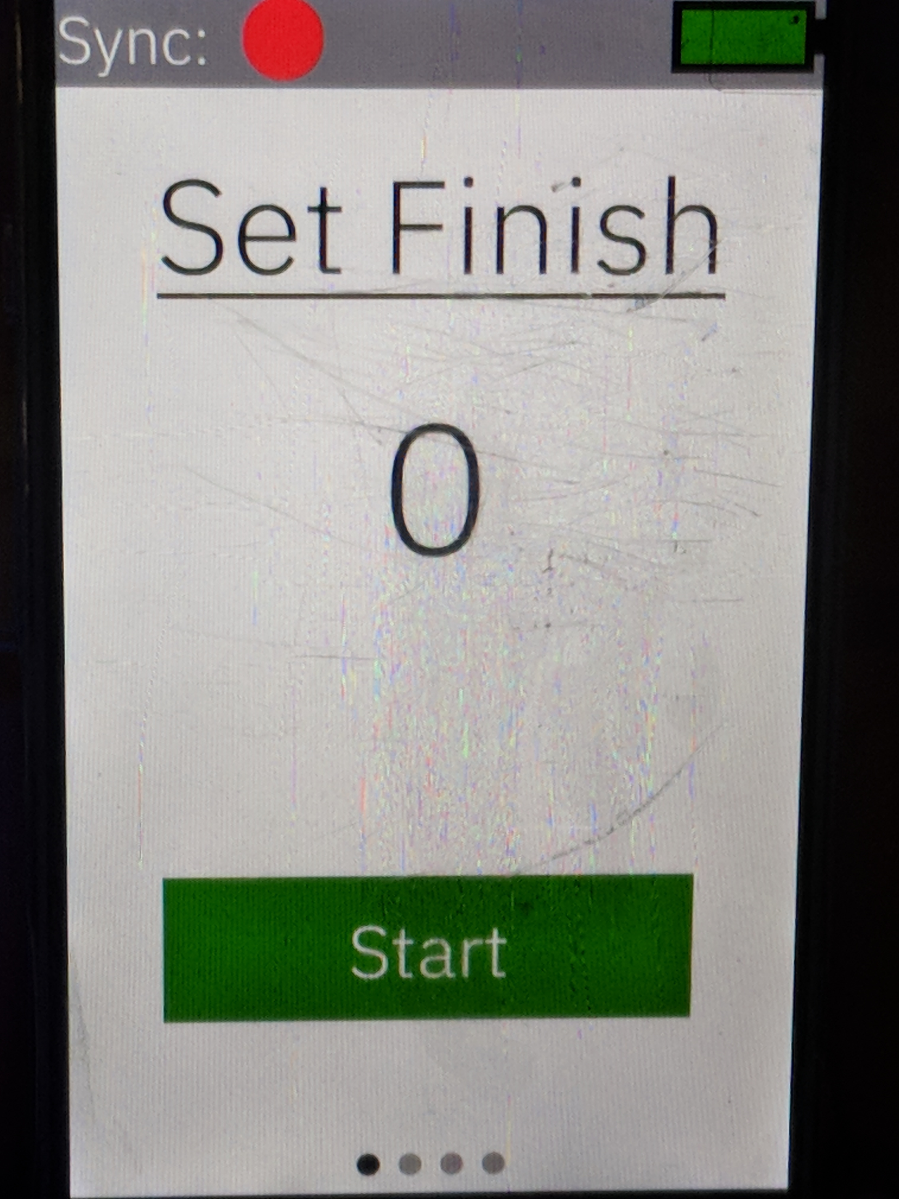
You will notice on interval pieces that the screen will automatically go the "Set Finish Distance" page. To set the distance, you simply click start and the LIDAR Lite will start measuring distances and reporting it back to the RPi. Point the LIDAR Lite at an object where you would like to line up your finish line and hit set. If you hit cancel if will set the distance to whatever it was set at last, if nothing was set then it will go back to 0.
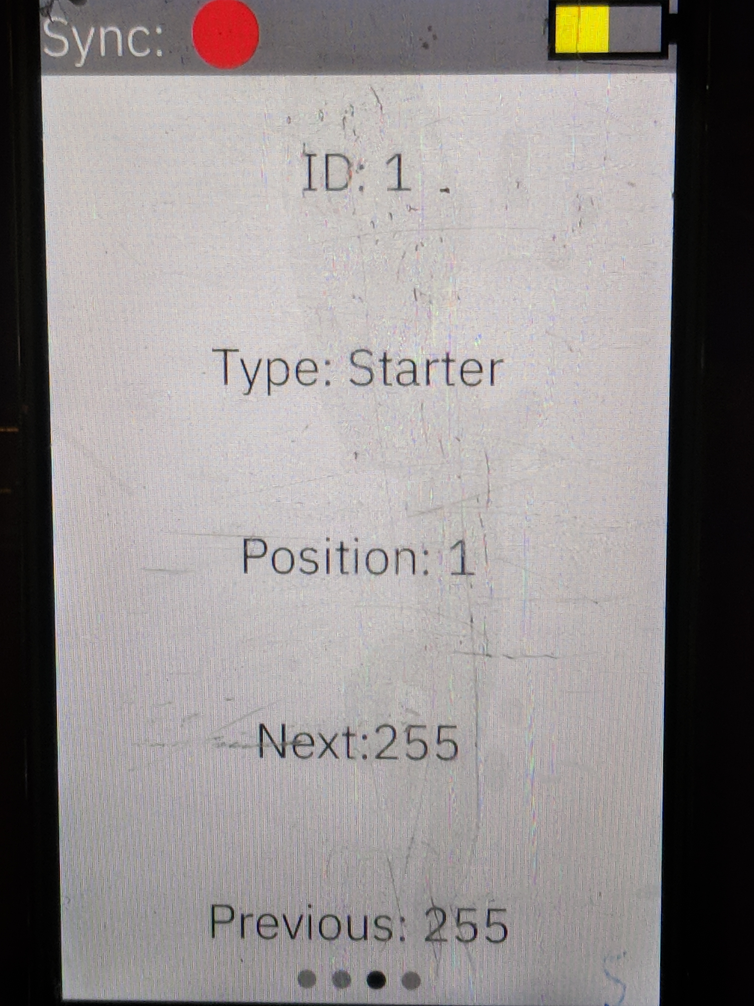
On all device you will notice that there is a "Status" page. On the "Status" page you will see that there is both a "Position" and a "ID". The "Position" on all devices will default to 1, and the device ID of each device is set permanently by writing it to the EEPROM of the Arduino when you set it up.
Because the network is set up similarly to a doubly linked list(https://en.wikipedia.org/wiki/Doubly_linked_list), every device knows about the device that is at the position before it and the device that is at the next position. Because currently only a start and finish are supported there are only two positions that are relevant: 1: Start 2: Finish and because currently you are always adding the finish from the start you always want the position you are adding to be 2.
This is the device ID you specified when setting up the Arduino. This can be found on the status page of the finish device.
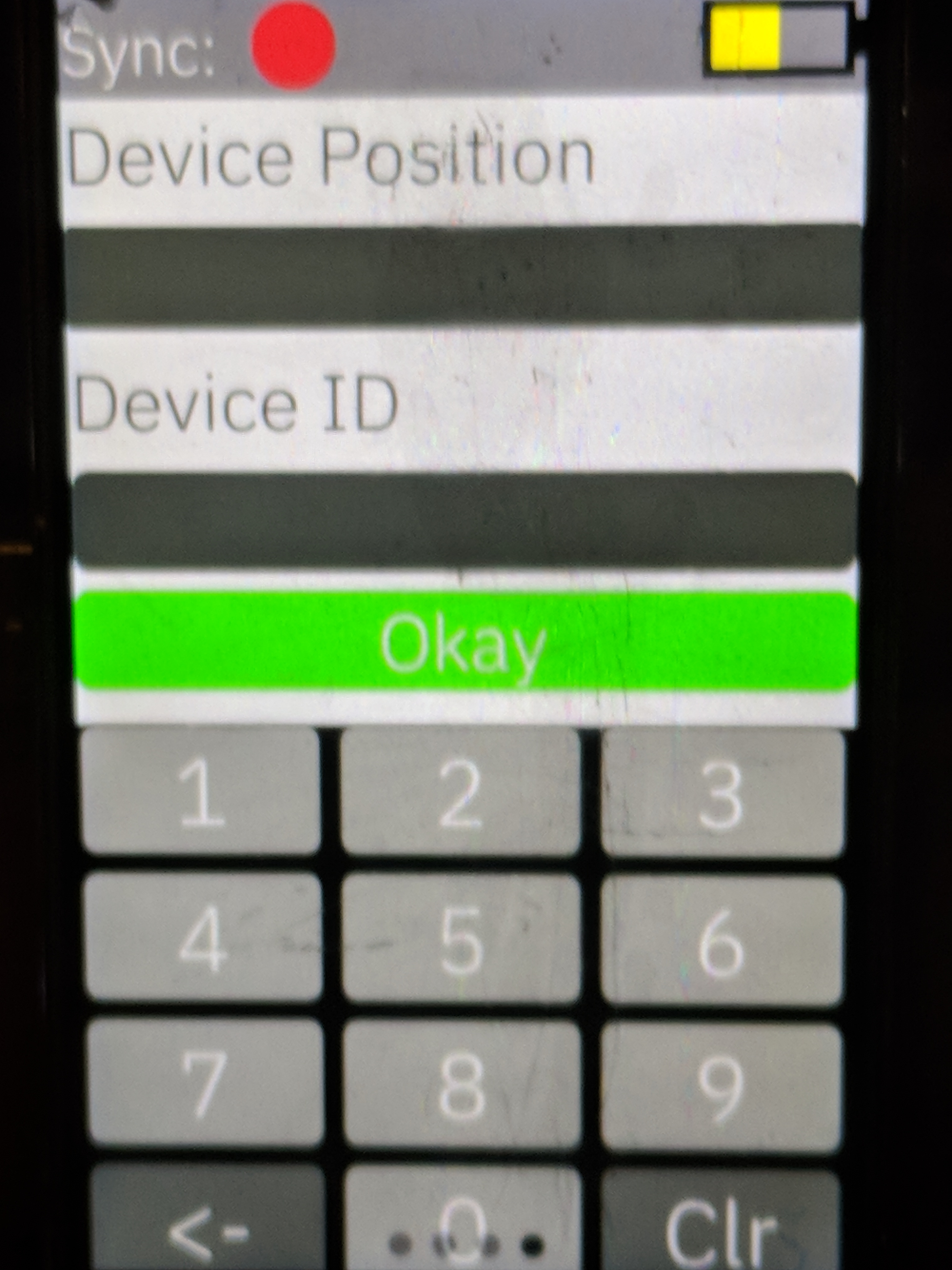
To synchronize the device, enter the position you want to add to the network (2) and the device ID of the device you want to add. For example, if I had a Start piece which had the ID=4, and a finish piece with the ID=9, on the "Add Device" page I would want to tap the text box I want to edit and for "Device Position:" I would enter 2, and for "Device ID" I would enter 9.
Once the sync is complete you will notice that in the status bar of both devices that the red circle next to "Sync:" are now green. This indicates that the sync was successful.
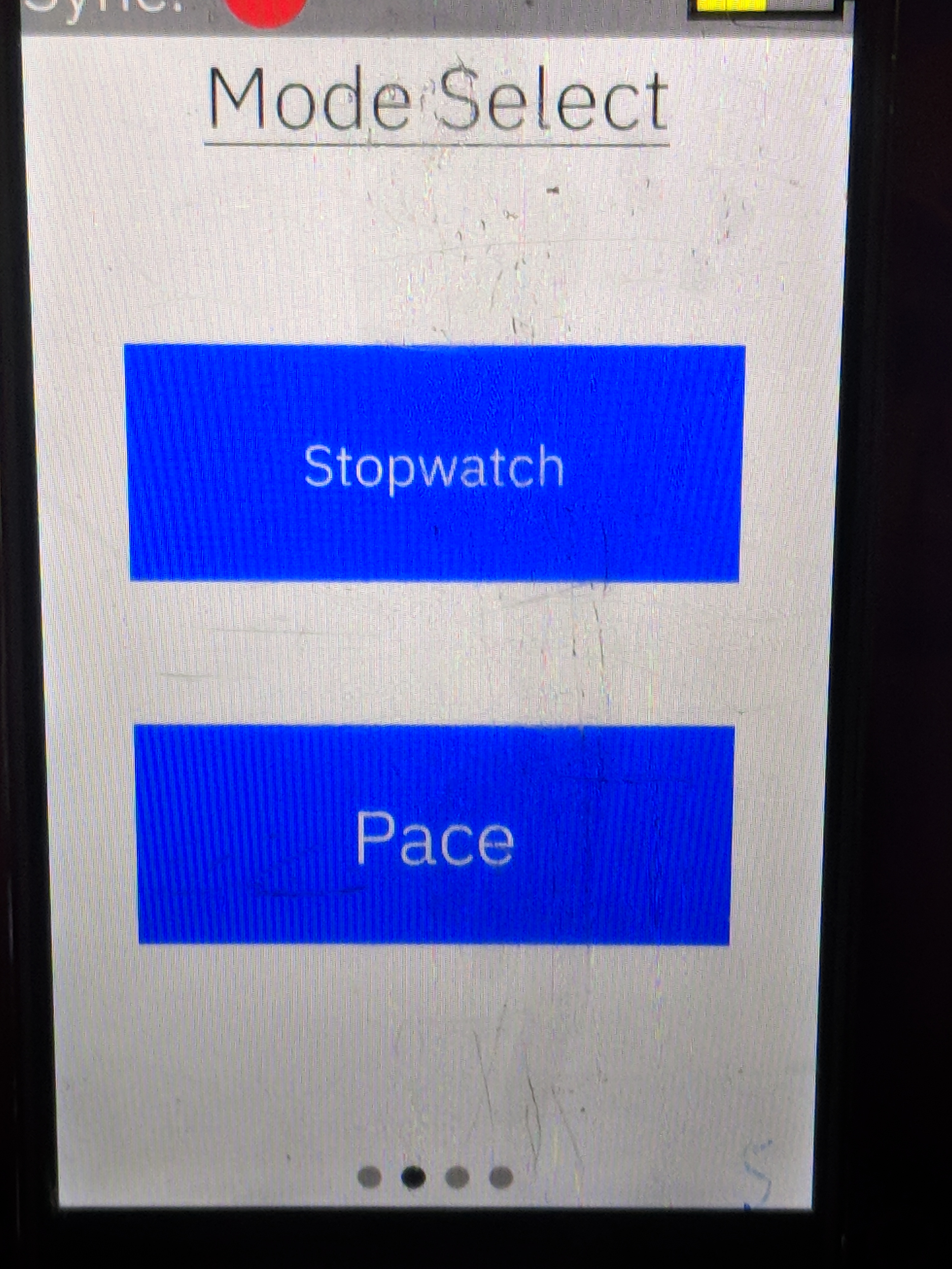
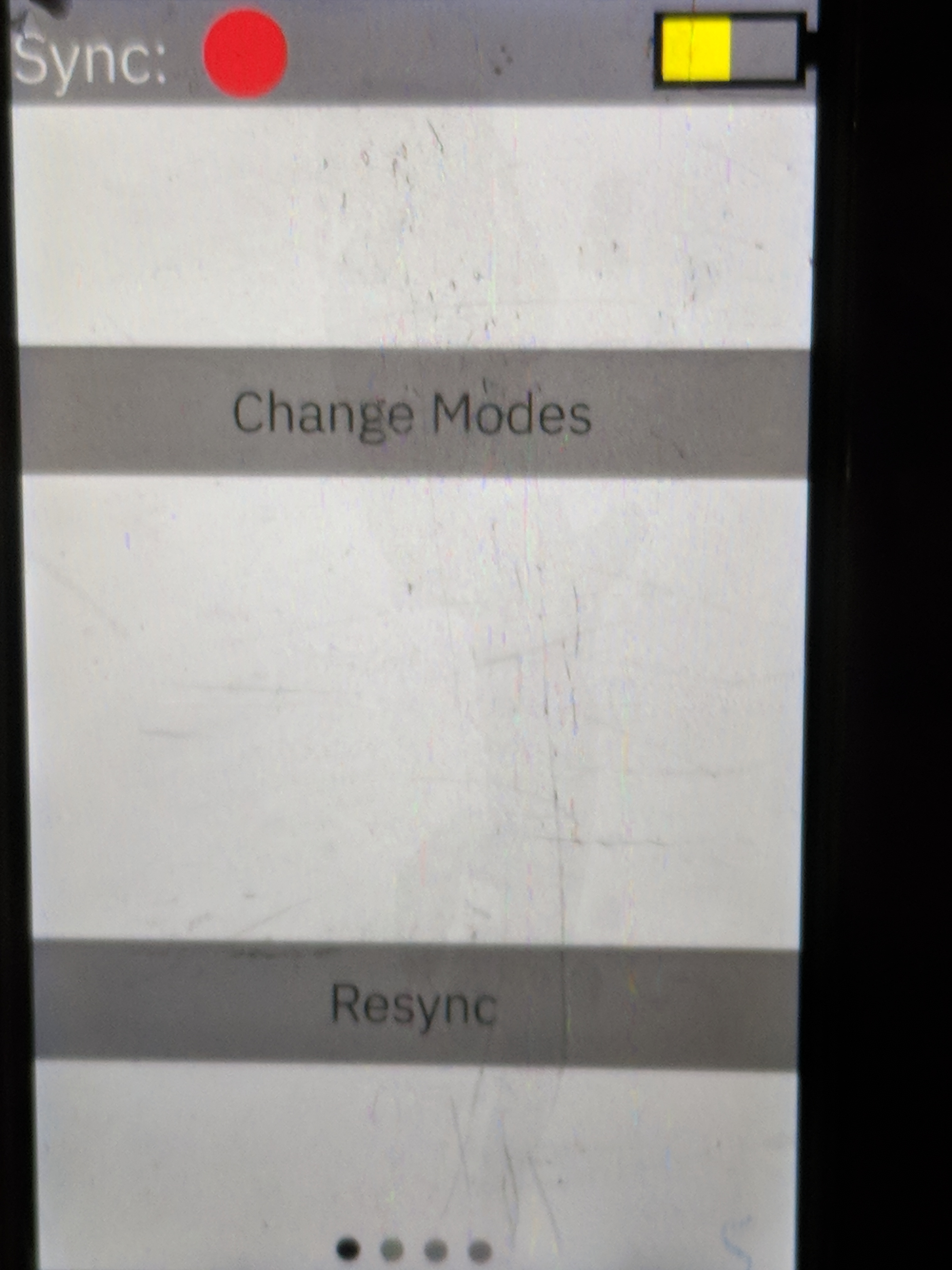
The WirelessTimer software offers different modes in which to time, currently it offers stopwatch mode, and pace mode. On the "Mode Select Page" you will find a button for both options, and if you go to the "Options" page you will find a button "Select Mode" which allows you to return to the "Mode Select" page if you would like to switch from one mode to the other.
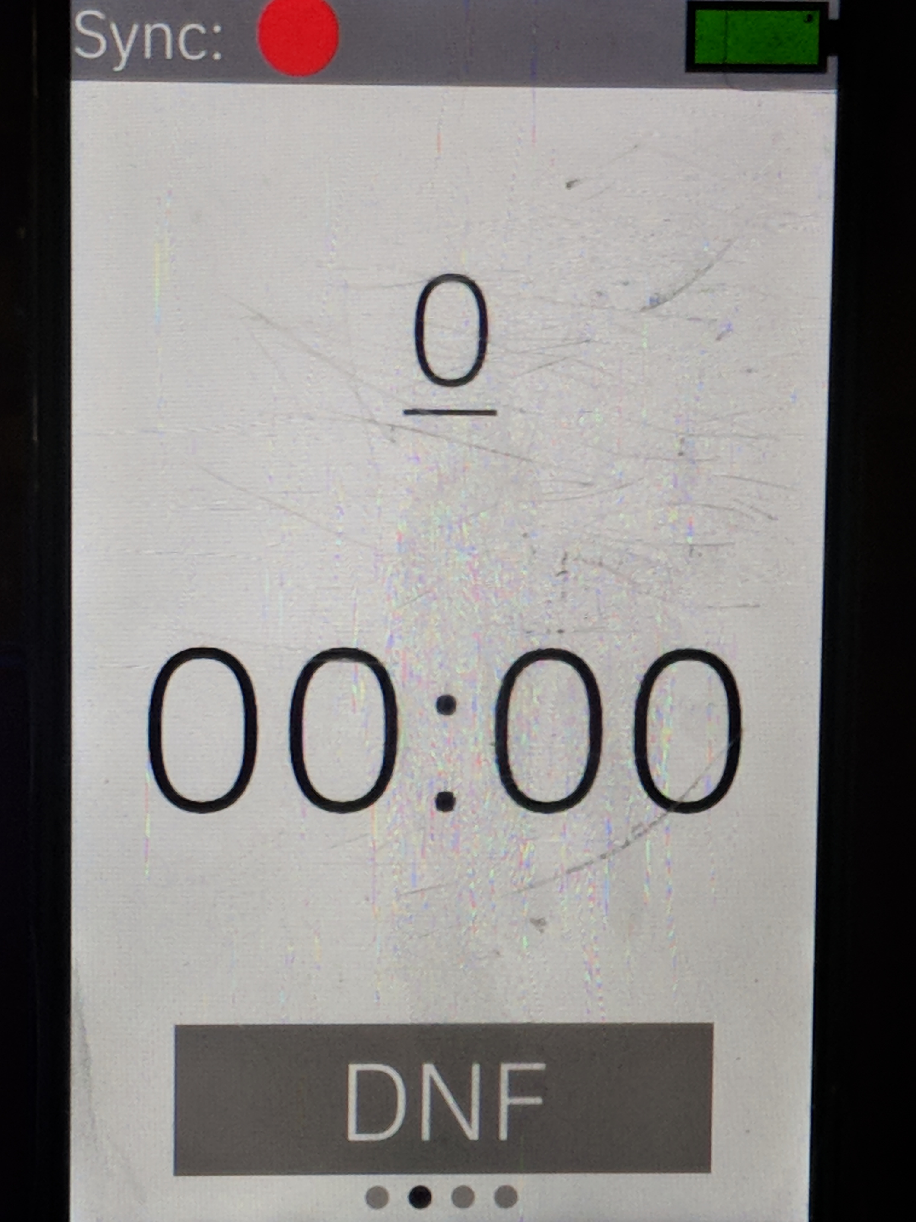
This mode is the most basic mode in which to time. The times start as soon as the magnetic contact opens and will stop when something makes the LIDAR Lite pick up a distance less then 15cm of what the finish distance was set to. You also have the option to manually DNF (Did Not Finish) the racer as well if they won’t be completing the run. This mode allows for as many people on course as you would like and will not automatically DNF anyone.
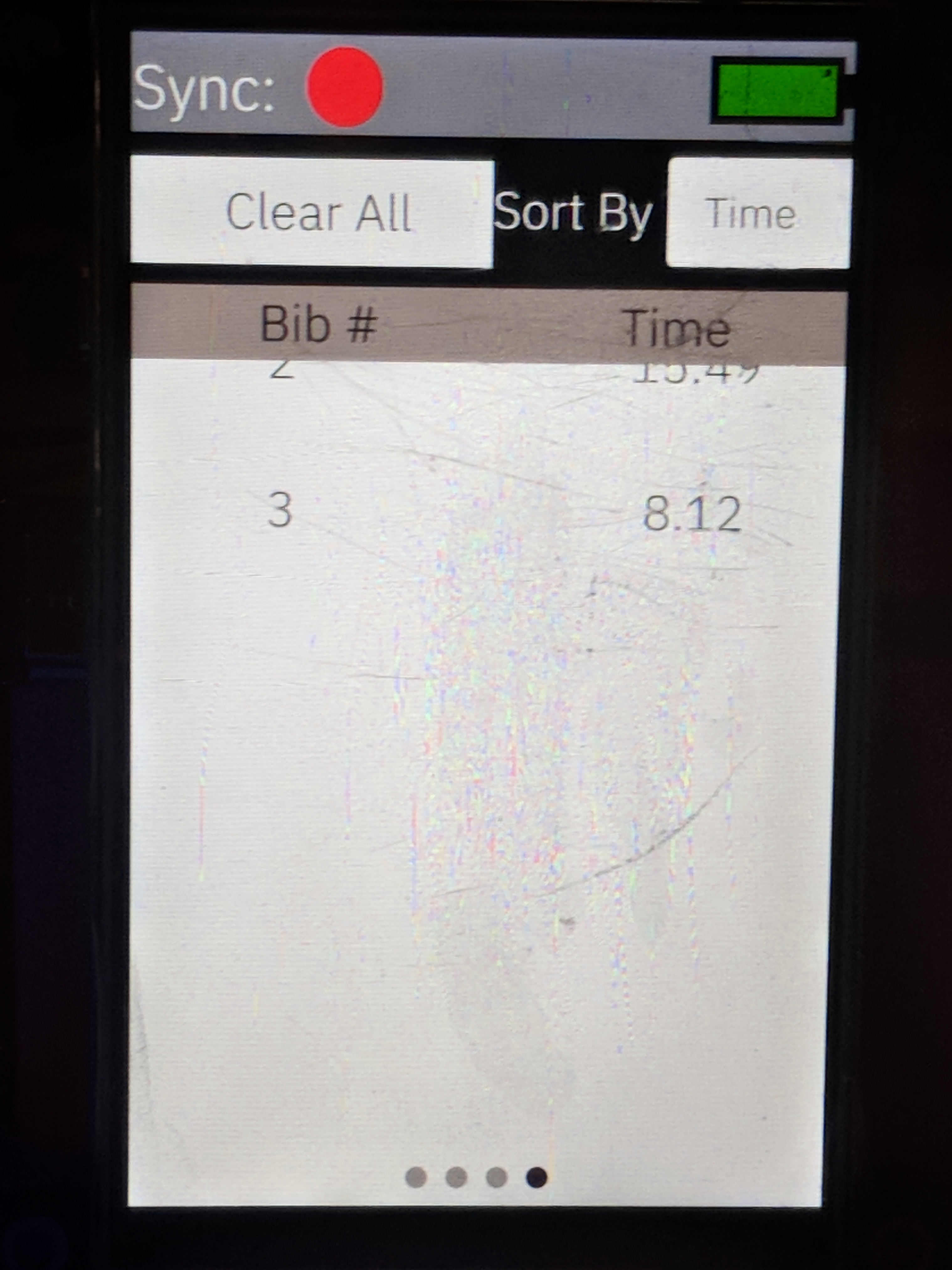
In pace mode a reference time is used to determine weather or not something crossing the finish line is likely to be the thing we expect to be crossing the line. Currently the threshold to test against the pace time is 10 seconds. For example if you select pace mode the first person to go down the course will have their finish time recorded as the pace time, and from then on when someone starts the time any thing that triggers the finish which is 10 seconds faster than the pace time will not trigger the finish, and if the time goes more then 10 seconds over the pace time then the finish will automatically trigger a DNF.
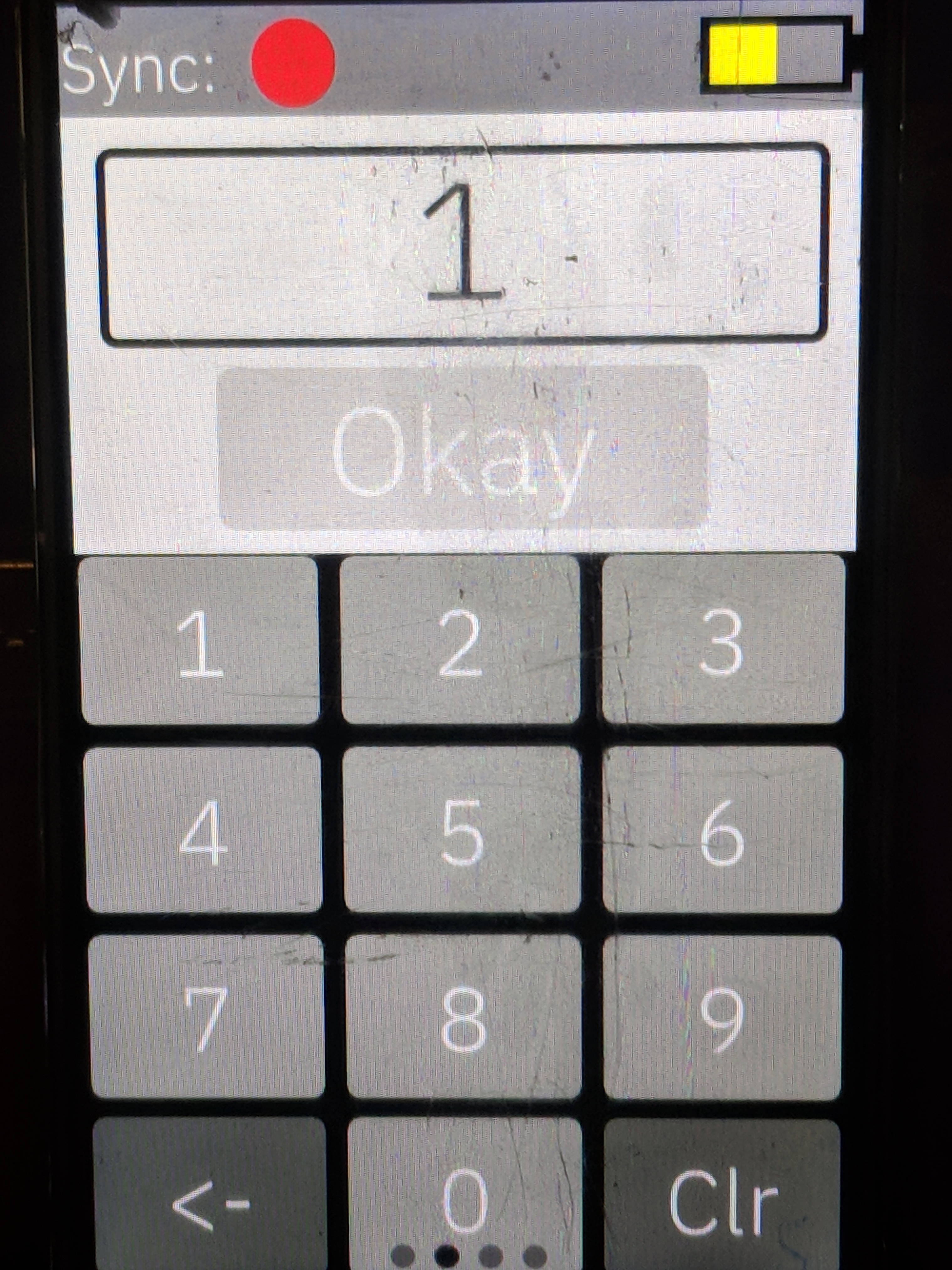
Once you know which mode you would like and select that button a keyboard will appear with a text box above it. The text box holds the bib number of the racer about to start and defaults to 1. If the start is not synchronized the "Okay" button will be grey and disabled, if it is green the it is ready to go!
In stopwatch mode it is very straight forward you simply enter a bib number, hit "Okay" and open the magnetic contact switch and the time will be started. You can do as many racers on the track at one time as you would like.
In pace mode you will enter the number of the bib you would like to, hit "Okay", and then open the magnetic contact switch, however in pace mode if there is no pace time set then the start will stay with the "Ready!" page with a loading indicator bellow it until the racer completes there run, at which point the time of the racer will be transmitted back to the start, and from then on the pace will be set at the first runners time, and the threshold will be 10 seconds. If the person setting the pace does not complete their run you can manually click "DNF" on the finish piece which will let the start know that a pace wasn't set and then the next racer will set the pace.