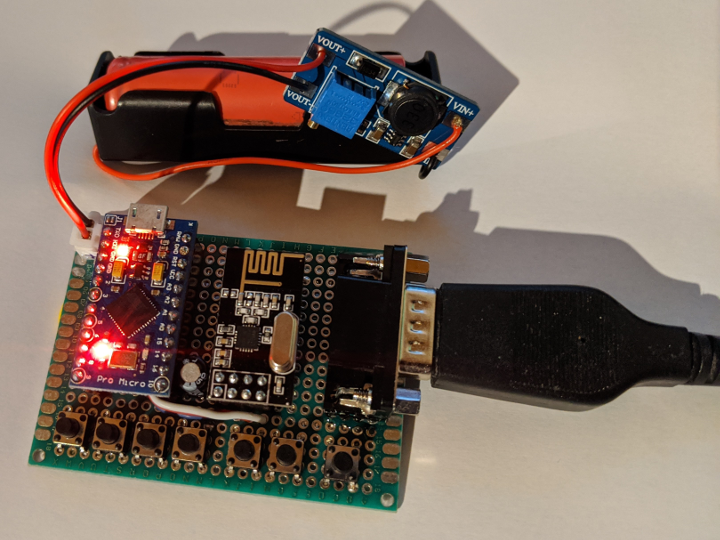
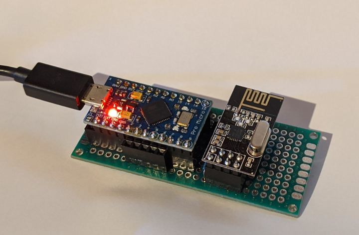
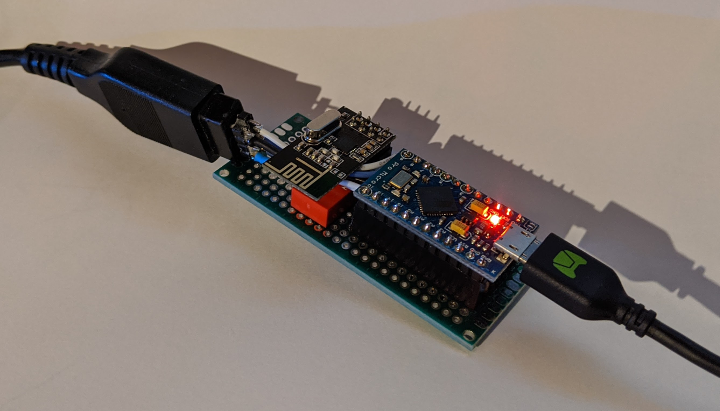
This is a very simple sketch that allows you to connect your "retro" C64 joystick on modern systems via USB. It requires an Arduino Micro (or other boards based on ATmega32u4 with native USB support).
To get things working with the TheC64, some modifications in the Joystick library and boards.txt are required. If you don't want to mess around with that, you can download pre-compiled versions, below.
It is now also possible to connect it wirelessly. This requires NRF24L01 modules. See further down for more info.
The latest version is 0.9.6-20200122a.
- Arduino IDE,
- Joystick library: https://github.com/MHeironimus/ArduinoJoystickLibrary
- NRFLite library: https://github.com/dparson55/NRFLite (for wireless operation only) This can be installed through the Library Manager in Arduino IDE.
- AESLib library: https://github.com/DavyLandman/AESLib (for wireless operation only)
For your convenience I have added pre-compiled .hex files. This is useful if you don't want to modify the Joystick library and mess around in boards.txt.
The latest pre-compiled binaries are for version 0.9.5-20200118a:
- For wired operation, download the standalone version.
- For wireless operation, you need to download the server and the client. (This is a version that does not use encryption.)
For wired operation a single Arduino Pro Micro board (or similar) is required.
See below for instructions on how to connect the joystick to the Arduino.
The code should compile for the wired mode by default but you should ensure that only LOCAL_CLIENT is defined in RetroUSBJoystickConfig.h.
Compile and upload the sketch to the board.
Female joystick connector as seen at the end of the cable:
                 Joystick    Arduino Pro Micro
                        1 => N/C
   1 2 3 4 5            2 => Digital pin  3 (RIGHT)
 +-----------+          3 => Digital pin 10 (LEFT)
 | o o o o o |          4 => Digital pin  9 (DOWN)
  \ o o o o /           5 => Digital pin  8 (UP)
   +-------+            6 => N/C
    6 7 8 9             7 => GND
                        8 => VCC (+5V) *
                        9 => Digital pin  2 (FIRE)

*) VCC +5V is only required if the joystick consumes power. For most micro-switch joysticks, like "The Arcade" for example, this connection is not needed. The connection to GND *is* required.
Wireless operation requirements:
- You need two Arduino boards, and at least one should be based on a ATmega32u4 (i.e. with native USB support).
- Two NRF24L01 modules. NOTE: These modules run on 3.3V -- connecting them to 5V from the Arduino may fry them!
Additional dependencies: The "server" will be connected to the PC or other machine via USB and receives radio packets from the "client". The joystick is physically connected to the "client" board which sends the changes over the radio.
(I did research using an ESP8266 module. Initial experiments indicated there is too much processing overhead causing an annoying input lag.)NOTE: All radio communication is un-encrypted. If you believe that's a problem, use the wired solution, above.
See below for the connections for the NRF24L01 module. You will need to compile and upload two different sketches to the two boards.
For the "server" (the receiving part), ensure that only REMOTE_SERVER is defined in RetroUSBJoystickConfig.h, and LOCAL_CLIENT / REMOTE_CLIENT are not. Compile and upload the sketch.
If you want to use encryption, you will need to enable and modify the REMOTE_ENCRYPTION_KEY define in the file RetroUSBJoystickConfig.h. If this value is not defined, encryption shall not be compiled in.
The encryption feature is added to prevent packets from other remotes within radio range to get interpreted. It adds a minimal layer of security and privacy -- but it does not protect against so-called "replay-attacks". But it's "just" joystick movements, so, I guess it should be fine. :)
If you do decide to enable encryption, and you do not change the key value itself, this may result in the receiver interpreting packets from a secondary remote client within the range of the radio.
For the "client" (the sending part), ensure that only REMOTE_CLIENT is defined, and LOCAL_CLIENT and REMOTE_SERVER are not. Compile and upload the sketch to the other board.
The 8 pin NRF24L01 module should be connected to the following pins on both boards:
                     NRF24    Arduino Pro Micro
                         1 => Digital pin 14 (MISO)
       1 2 3 4           2 => Digital pin 15 (SCK)
     +---------+         3 => Digital pin A1 (CE)
     | o o o|o |         4 => GND
     | o o o o |         5 => Digital pin  7 (IRQ, yet unused though, so can be omitted)
     +---------+         6 => Digital pin 16 (MOSI)
       5 6 7 8           7 => Digital pin A0 (CS)
                         8 => 3.3V
- If the Arduino cannot initialise the NRF24 module, it will blink a LED repeatedly.
- In case of problems, you can enable
SERIAL_DEBUGin the fileC64JoystickBase.hto see more verbose operation in the Serial Monitor in the Arduino IDE (9600 baud).
Copyright (C) 2020 Hugo van Galen
This software is provided 'as-is', without any express or implied warranty. In no event will the authors be held liable for any damages arising from the use of this software.
Permission is granted to anyone to use this software for any purpose, including commercial applications, and to alter it and redistribute it freely, subject to the following restrictions:
-
The origin of this software must not be misrepresented; you must not claim that you wrote the original software. If you use this software in a product, an acknowledgment in the product documentation would be appreciated but is not required.
-
Altered source versions must be plainly marked as such, and must not be misrepresented as being the original software.
-
This notice may not be removed or altered from any source distribution.
THE SOFTWARE IS PROVIDED "AS IS", WITHOUT WARRANTY OF ANY KIND, EXPRESS OR IMPLIED, INCLUDING BUT NOT LIMITED TO THE WARRANTIES OF MERCHANTABILITY, FITNESS FOR A PARTICULAR PURPOSE AND NONINFRINGEMENT. IN NO EVENT SHALL THE AUTHORS OR COPYRIGHT HOLDERS BE LIABLE FOR ANY CLAIM, DAMAGES OR OTHER LIABILITY, WHETHER IN AN ACTION OF CONTRACT, TORT OR OTHERWISE, ARISING FROM, OUT OF OR IN CONNECTION WITH THE SOFTWARE OR THE USE OR OTHER DEALINGS IN THE SOFTWARE.


