Tlera Corporation offers a popular set of attitude and heading reference system (AHRS) boards known as the "Ultimate Sensor Fusion Solution" or USFS. The heart of the USFS is EM Microelectronic's EM7180 "Sentral" sensor fusion coprocessor, which uses PNICorp's “SpacePointTM” adaptive fusion algorithm. With proper sensor calibration, the USFS can readily provide heading accuracy of ~2deg RMS or better.
Many customers have found the USFS to be a good solution for their applications. However, there are two fundamental limitations to the Sentral sensor fusion solution:
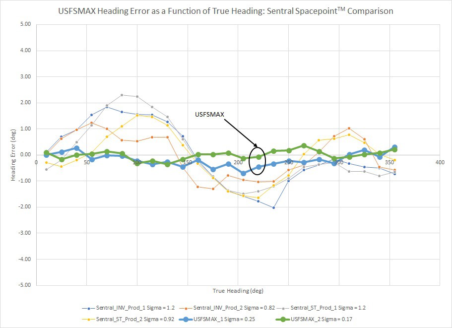
- The ~2deg RMS residual heading error level is dominated by uncorrected (sinusoidal) systematic sensor errors
- The SpacePoint adaptive algorithm is "Always on". In the case of external magnetic interference, the algorithm can adapt to local corruption of the geomagnetic field... Potentially giving bad heading results that can persist for several minutes after the magnetic interference has been resolved
Closer examination of the Sentral's residual heading error showed it to be remarkably stable as well as systematic. These facts convinced me that an improved sensor calibration method and user control over any adaptive elements in the fusion algorithm would be key areas to improve beyond the ~2deg RMS heading error level provided by the Sentral.
These were the primary motivating factors behind development of the "USFSMAX" motion coprocessor, documented in detail on hackaday.io. The actual coprocessor is Maxim Integrated's MAX32660 Cortex M4F microcontroller. The MAX32660 is paired with ST Micro's LSM6DSM accel/gyro, LIS2MDL magnetometer and LPS22HB barometer all of which are "Best in breed" contenders among the various MEMS sensors currently available.

The USFSMAX hardware is an excellent platform for enhanced sensor calibration and fusion algorithm development:
- Lots of horsepower - 96MHz Cortex M4F CPU
- Lots of memory - 256KB flash, 96KB SRAM
- High-quality, stable MEMS sensors
- 1MHz asynchronous I2C slave bus for fast data transfer to the host MCU
Over the period of about two years, I have made a great deal of progress in terms of both the fusion and sensor calibration methods. These advances have been incorporated into the USFSMAX motion coprocessor hardware to provide results that are significantly better than those from the Sentral. Calibration and characterization of the first four prototype USFSMAX units showed RMS heading error ranging between 0.25 and 0.35deg.

Furthermore, the sinusoidal character of the heading error has been largely eiminated, indicating that the vast majority of systematic sensor errors have been effectively corrected. This level of accuracy can be enabling for many user applications in a smaller form factor and at a fraction of the price of other AHRS solutions.
But perhaps the most important advance is in the area of improved practical performance. Typically, the sensors can be well-calibrated after bench procedures conducted under controlled conditions... But the actual practical performance degrades during real-world usage out in the field. After extensive testing and observation it became clear that degraded heading accuracy is almost entirely driven by residual "Hard iron" effects. I have developed an in-situ dynamic hard iron (DHI) corrector that is capable of measuring and subtracting any hard-iron-like magnetic interference once the USFSMAX has been installed in a test object for use. To demonstrate the DHI corrector's efficacy, a small rare-earth magnet was attached to the USFSMAX's test fixture after the bench calibration was done. The DHI corrector was reset and "Taught" by tumbling the USFSMAX in 3-D. The results show that with the rare earth magnet attached the heading is unusable (RMS heading error 99.4deg) and that the DHI corrector recovered the heading accuracy back to the same level observed immediately after the bench calibration procedure (RMS heading error 0.18deg).

Note: DO NOT enable the DHI until you are ready to train the corrector under the method and controlled conditions described below. Enabling the DHI without following the proper training procedure can result in unstable output data rates and erroneous heading results. The DHI corrector programmed into the USFSMAX's firmware is adaptive, similar in nature of the Sentral's SpacePointTM algorithm but with some key differences:
- The DHI corrector can be enabled or disabled at startup by user command from the host MCU
- If there is a valid DHI correction in the USFSMAX's EEPROM, it is loaded and used at startup if the DHI corrector is enabled
- The DHI corrector starts collecting data at startup/reset only when there is no valid DHI correction in the EEPROM and then stops once the new hard iron correction estimate is complete. It is *necessary to reset the DHI corrector from the host MCU (clearing the DHI corrector's training data buffer) and consciously train the DHI corrector under known/controlled conditions
- The new DHI correction estimate is automatically stored in the USFSMAX's EEPROM upon completion
- The DHI corrector can be reset at any time by user command from the host MCU. Once reset, any hard iron correction estimate in the EEPROM is invalidated and data collection for a new correction estimate begins
- When the new hard iron correction estimate is complete, a quality figure-of-merit for the estimate is available as well. The user can then choose to let the estimate stand or reset the corrector and try again
So, the user can decide when to use the DHI corrector and the timespan over which the correction data set is collected is limited. If the user decides the hard iron correction estimate has become stale, the corrector can be reset at will to begin a new estimate. If transient magnetic interference is not a large issue, the USFSMAX will rely on the last saved hard iron correction estimate until a new one is generated. The quality of the latest correction estimate is judged by the R-squared metric. When the variation in the magnetic data set NOT explained by the hard iron correction estimate tends to zero, R-squared tends to 1.0. For the moment it is up to the user to interpret the R-squared value and either accept the hard iron correction estimate or reject it and reset the corrector.
As a final matter, there are actually two versions of the DHI corrector: 3-D and 2-D. They are both capable of yielding excellent hard iron correction estimates but both are included for different use cases of the USFSMAX. Simply stated, if the test object to which the USFSMAX is attached is small/light and can easily be tumbled in 3-Space, the 3-D corrector is the best choice. If the test object is unwieldy or its motion is largely constrained to the X-Y (horizontal) plane the 2-D corrector is a better choice. Both correctors collect 150 data points at enforced separation before calculating the final correction estimate. When the estimate is complete, the hard iron corrector status bit in the calibration status register toggles true and the R-squared value populates the appropriate data registers. The desired corrector can be chosen at startup by user command from the host MCU. To get the best hard iron correction estimate:
- 3-D corrector: Tumble the USFSMAX (attached to the test object) in 3-Space trying to sample all possible orientations. The intent is to randomly collect training data that uniformly covers the response surface of the magnetometer triple. In a good magnetic environment (no significant stray fields) the 3-D corrector should complete the new hard iron estimate in ~60 - 90s of random rotation. If done properly, R-square >= 0.95 is quite normal
- 2-D corrector: Rotate the USFSMAX (attached to the test object) in the X-Y (horizontal) plane. Better hard iron correction estimates are obtained when the USFSMAX is within +/- ~5deg of level during horizontal rotation. In a good magnetic environment (no significant stray fields) the 2-D corrector should complete the new hard iron estimate in ~15 - 20 rotations in the X-Y plane. If rigorously constrained to be level (pitch = roll = ~0) during rotation, R-square >= 0.95 can be expected. If not rigorously level during horizontal rotation, R-squared tends to be smaller. If R-squared >= ~0.75, the hard iron correction estimate is generally still useful
This repository contains example host MCU Arduino sketches to demonstrate basic use of the USFSMAX motion coprocessor. The USFSMAX board is typically soldered onto pin headers and then connected to the host MCU using a solderless ptototyping "Breadboard" or by plugging into female pin header sockets soldered onto the MCU board.
Construction Note: Recent testing has shown that overheating the magnetometer can undermine calibration validity and cause loss of heading accuracy. Caution should be exercised while soldering pin headers or other connectors to the USFSMAX board. We specifically recommend:
- Use fine gauge, high quality 60-40 or 63-37 Sn/Pb electronic grade flux-core solder
- Sn-based ROHS-compliant solders are not recommended due to their higher melting/flowing temperatures
- Use a good quality soldering iron with a fine, clean tip. It should be the right temperature to cause solder to flow between the pin and plated through-hole in a few seconds. Too cold will require excessive contact time for the solder to flow, overheating the board. Too hot can cause damage to the plastic pin header block and delamination of the plated through hole pads
- Insert both rows of solder pins on both sides of the USFSMAX board, align them properly and hold them in place
- Verify that the soldering iron and solder quickly make a good joint by testing on the “INT” or “ADO” pins first
- The “GND” and “3V3” pins are the closest to the magnetometer; try to keep soldering iron contact down to 1 – 2s. Only electrical contact is required for these pins
- DO NOT solder the pins sequentially “In a row” down one side. This concentrates too much heat into a small area of the USFSMAX board. Instead, solder one pin and then skip to the next pin that is furthest away. If there is any question that the board is getting hot, stop and let it cool
This version is written for the Tlera Dragonfly STM32L476 development board using the STM32L4 core for the Arduino IDE. The USFSMAX breakout board can be connected to the MCU developmet board on a prototyping "Breadboard" or it can be "Piggybacked" using pin headers.
This version was tested using the Teensy 3.2 and 3.6 development boards in the piggyback configuration. The Teensy-specific "i2c_t3" I2C library is used here and will need to be installed in your sketchbook folder.
This verson was tested using the Tlera ESP32 development board, which has been retired. However, the code can be used with the ESP32 development board of your choice. For your particular board, simply go to the "config.h" tab and re-define:
- "INT_PIN" USFSMAX data ready GPIO
- "LED_PIN" utility LED GPIO
- "USFS_GND_PIN "GND" GPIO (Piggyback configuration)
- "USFS_VCC" "3V3" GPIO (Piggyback configuration)
- "SDA_PIN" I2C data GPIO
- "SCL_PIN" I2C clock GPIO
The sketch configures the USFSMAX at startup and demonstrates the basic AHRS functions and sensor data acquisition according to the USFSMAX register map included in this repository. The DHI corrector can be enabled/configured in the "config.h" tab of the sketch to evaluate its operation in 2-D and 3-D modes. The sketch's serial interface supports reset of the DHI corrector selected at startup.
All bench calibrations of the accelerometers and magnetometers are stored in the USFSMAX's EEPROM and are not intended to be modified by the user at this time.
The gyroscope biases are calculated at startup and are stored in the USFSMAX's EEPROM. The gyroscope bias calculation routine detects unwanted motion and resets the data buffers if the USFSMAX is bumped during gyroscope calibration. However, it is a good idea to take care to not disturb the USFS during gyroscope calibration. Gyroscope calibration can be selected from the sketch's serial interface at any time.
The DHI correction function is activated by defining "ENABLE_DHI_CORRECTOR" as "0x01". The 2-D corrector is selected by defining "USE_2D_DHI_CORRECTOR" as "0x01", otherwise the 3-D corrector is used instead. These definitions along with some simple instructions are located in the "BASIC SETUP" section in the "config.h" tab of the sketch.
If the 3-D DHI corrector is selected and active, data collection for a new hard iron correction estimate begins at startup. Tumble the USFSMAX (attached to the test object) randomly in 3-Space until the "Dynamic Hard Iron Correction Valid" field on the serial interface toggles from "0" to "128". The new value of the R-squared will be displayed as well.
If the 2-D DHI corrector is selected and active, the basic procedure and serial interface response is similar. However, the USFSMAX and test object should be rotated in the horizontal plane (NOT in 3-D) for several revolutions until the corrector completes the hard iron correction estimate. The closer to level the pitch and roll attitude of the USFSMAX is held during 2-D rotation the better the hard iron correction estimate (and the larger R-squared) will be.
The I2C slave address of the USFSMAX is currently set to 0x57. There are plans to make the I2C slave address user-selectable and this feature should be available soon. An important aspect of the USFSMAX's I2C slave bus is that there is always a finite delay between when the host MCU requests to read data and when that data is available to be read. Consequently, the USFSMAX will work best with host MCU's that support I2C clock stretching.
It should be noted that the USFSMAX data registers are set up for efficient I2C data transfer by "Burst reading". That is, a starting data register is specified in the I2C transaction and additional data registers are read sequentially for the total number of bytes specified in the transaction. To improve overall I2C read request response time to the host MCU, not all data registers can be the starting register of an I2C read transaction. Data registers that are directly addressable at the beginning of a read transaction are highlighted in yellow in the register map. So, for example, if a user wanted to read just the two Y-axis gyroscope sensor data bytes from registers 0x07 and 0x08, that is not supported. Instead, the read transaction would begin at register 0x05 and be four bytes long to include the two Y-axis gyroscope data bytes desired.
Your local geomagnetic constants are necessary to achieve the best heading accuracy. The constants in question are:
- Vertical field strength (M_V)
- Horizontal field strength (M_H)
- Magnetic declination (MAG_DECLINATION)
These constants are available from online calculators for your latitude and longitude. Once your geomagnetic constants have been looked up:
-
Define an entry for your location in the "Magnetic Constantants" section of the "config.h" tab
Example:
#define SUNNYVALE_CA_USA -
Define a new magnetic constants block in the "Magnetic Constants" section of the "def.h" tab
Example:
#ifdef SUNNYVALE_CA_USA #define M_V 41.8128f #define M_H 23.2519f #define MAG_DECLINIATION 13.2197f #endif -
Comment out all location definitions in the "Magnetic Constants" section of the "config.h" tab except for your own