Home
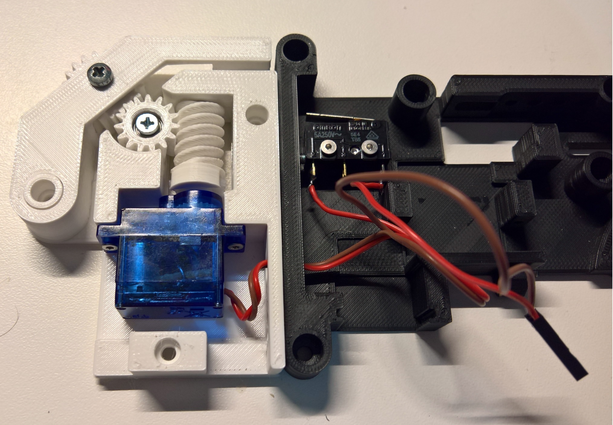
This assembly replaces the overhanging tape remover form the original design by using a hobby servo motor (SG90) or geared motor (N20) and a worm drive. It was design in OpenSCAD and offers the option to be tailored to everyones specific needs. You could also just print the prepared versions.
On word on screws for mounting rotating parts: This assembly was designt to make moving parts run on the screw head not the actual threaded part of the screw.
This depends on version but just to list some parts:
-
motor
- SG90
- needs to be turned into a constant rotation geard motor (remove rotation limits and electronics)
- see Servo Mod
- requires M2 screws at least 6 mm long
- N20:
- requires M1.6x4 mm screws and N20 adapter to be printed
- 300 rpm version is standard and should work
- (200 rpm and 150 rpm can be selected in customizer but are not tested)
- SG90
-
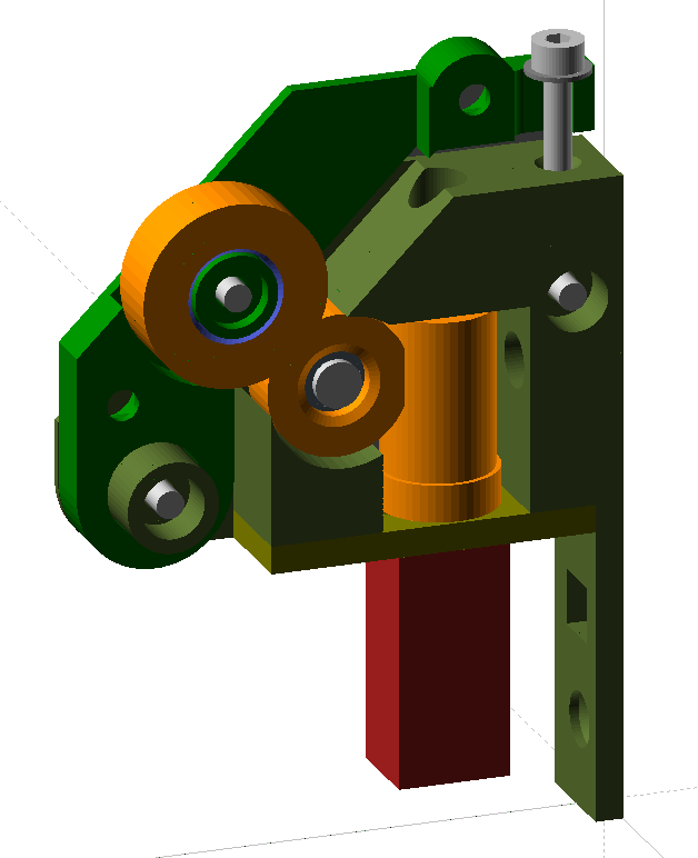
worm gear
- mounted with a bearing 683 + screw countersunk M3x8
- or mounted with a screw M3x8 and a shim
- pinion 1 (mounted on 683, screw or metal pin)
- pinion 2 (mounted on post or metal pin)
-
case (will be screwed to backside of the feeder assembly)
- countersunk screw to mount to feeder
- flat head M3x8 to close lid
-
lever for pinion 2, will come in two pieces
- assembled with M3x6
- tensioned with M3x16 and shim against case
- lid to close case
- SG90 as a drive flat head Din 912 M3x6 and shim 0.5 mm thick
- worm gear mounted on screw and shim
- pinion 1 mounted with flat head Din 912 M3x6
- pinion 2 mounted on post
- N20 as a drive
- worm gear mounted on bearing 683 + countersunk M3x8
- pinion 1 mounted on bearing 683 + countersunk M3x8
- pinion 2 mounted on pin
or choose with available parts in mind
I designed the parts to use specific layerheights for nice fits and teight tolerances. First layer height needs to be the same as layer height or multiples of layer height (eg. for 0.125 mm use 0.25 mm for first layer).
- case and lever
- layer height: 0.25 mm (or 0.125 for the looks)
- extrusion width: 0.45 mm
- worm gear
- layer height: 0.125 mm (or 0.0625 for lowes friction)
- extrusion width: 0.45 mm
- pinion 1 and 2
- layer height: 0.125 mm (these dont need 0.0625)
- extrusion width: 0.45 mm
- use raft to avoid elefant foot effect or a perfectly calibrated first layer
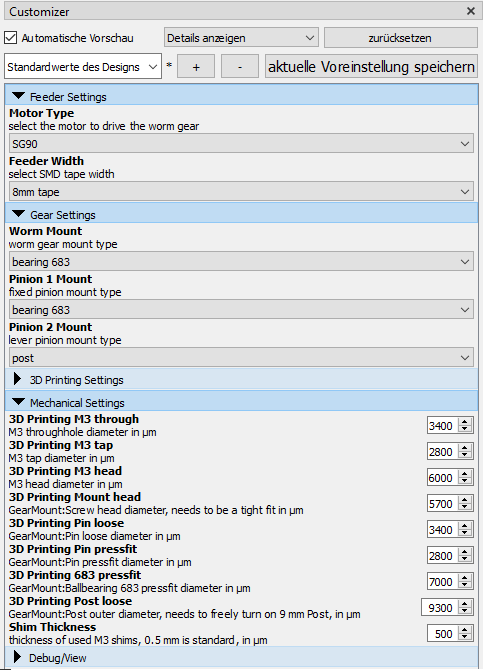
You may want to do this to fit some very specific use cases or trim the 3D model to your 3D printer.
- Download and install OpenSCAD
- Have a look around in the customizer to understand the model Espeecially the Tab "Debug/View" will help you with that
- Customize to your heart's content and give some feedback if you think others may benefit
- prepare case: mount case to feeder body
- prepare motor:
- for N20 mount motor to N20 adapter with M1.6 screws
- prepare worm gear:
- for worm gear mounted on bearing:
- mount bearing to worm gear with countersunk screw
- attach worm gear on motor
- for worm gear mounted on screw: mount worm gear with Din 912 M3x8 and shim to case
- for worm gear mounted on bearing:
- mount motor to case
- mount pinion 1
- assemble lever
- mount lever to case
- close assembly with lid