Multiple inputs and multiple outputs (MIMO) technology is one of the most promising technologies in the upcoming 5G mobile communication. A compact 4×4 MIMO antenna system is proposed to operate between 3.4 to 3.6 GHz (centred around 3.5 GHz) for future fifth-generation (5G) technology mobile broadband services. Initially, a single element antenna has been embedded on a mobile terminal and its performance has been tested based on some simulation studies. The proposed antenna is radiating in the desired frequency band and is expected to reduce the mutual coupling between the antenna elements. The antenna offers about 30% impedance bandwidth.
5G technology has changed the means of mobile phone usage by providing very high bandwidth. In the field of mobile communications, 5G technology is fast, high-capacity and very effective [1]. To design a completely wireless world, 5G demands the integration of the network. Is a very powerful technology and is expected to become very popular in the next few years [2]. A MIMO antenna, which is an established wireless communication technique that transmits multiple data signals simultaneously over one radio channel, is used for the 5G technology [3].
MIMO antenna is an upcoming and emerging technology employed in wireless communication in which multiple antennas are used at both the source (transmitter) and destination (receiver)[4]. By the capacity of radio frequency (RF) systems, MIMO creates a more stable connection and less congestion which means a reduced quality of service. The main advantage of MIMO is to increase the data rate in a communication system. The primary advantages of MIMO antenna include higher reliability without the need for extra power and bandwidth, maximum coverage, less error, better quality in transmission[5]-[6].
5G technology has extraordinary data capabilities and can provide huge unrestricted call volumes and infinite data broadcast within the latest mobile operating system [7]. For the last few years, several advanced designs of MIMO antenna have been which are compact and smaller in size [8]. Integrating multiple antennas in the portable mobile terminal is extremely challenging due to the strictly limited space. Multiple antenna designs are one of the hottest topics in the 5G MIMO system.
The target is to design a compact MIMO antenna that consists of four tightly-arranged elements in it. A MIMO antenna design that can have the lowest mutual coupling is the primary goal. So if we can add an inductor at the current minimum location or a capacitor at the current maximum location of two elements, it can reduce the mutual coupling significantly. It's an ongoing project. Before exporting the performance of the 4 elements MIMO, initially, the bandwidth and the radiation properties of the single antenna element have been studied this semester. The configuration of the antenna is presented in the next section along with some representation results.
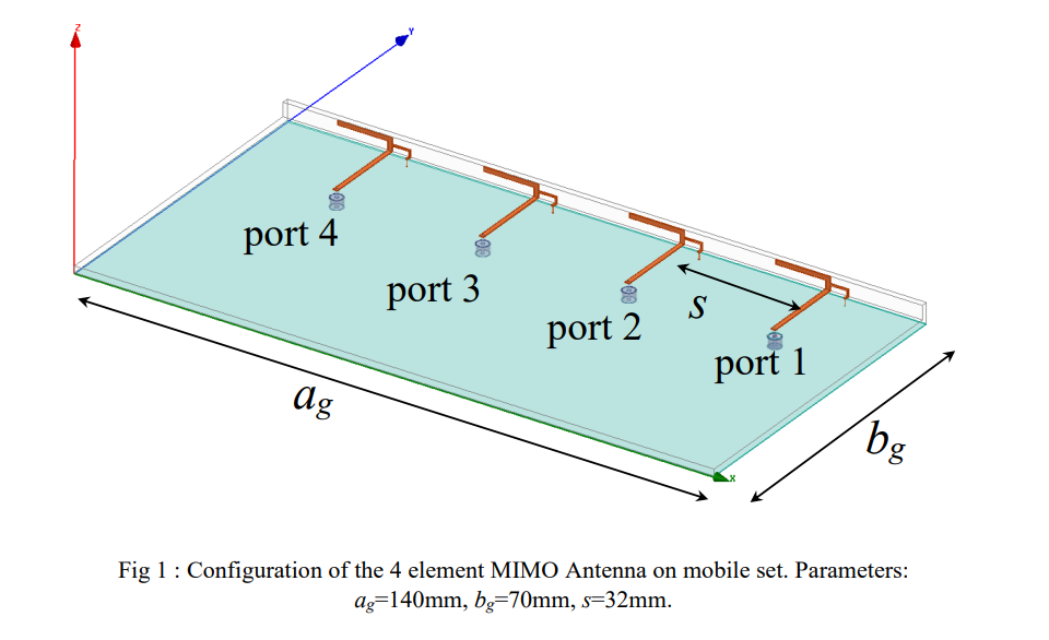
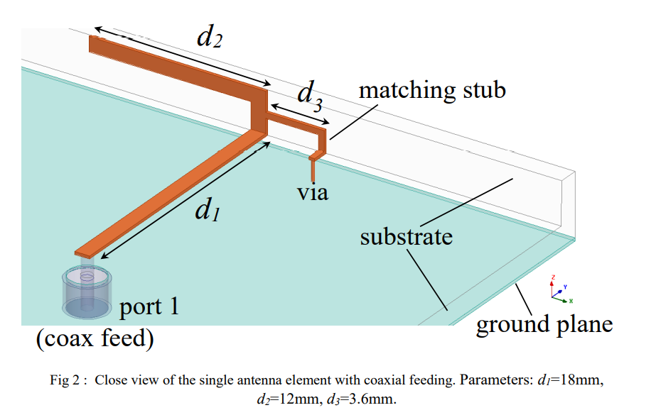
Figure 1 shows the configuration of the proposed MIMO antenna with 4 radiating elements. This configuration will be tested later for its mutual coupling performances. All 4 elements are excited through a coaxial cable. All parameters have been optimized based on the simulation results obtained using commercial simulator Ansys HFSS.
At this moment the performance of a single element has been tested. The antenna configuration
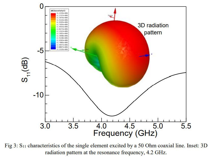
is shown in Fig. 2. Simulated results are presented in Fig. 3 and 4. Fig. 3 shows the simulated
S11 characteristics of the antenna using a single element. The antenna is radiating between 3.6-
4.9GHz covering the 5G band of mobile communication. The antenna is resonating at 4.2GHz
and showing approximately 30% impedance bandwidth. 3D radiation pattern at 4.2GHz is also
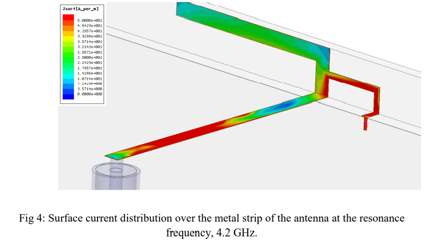
included in the inset. This shows good coverage of the mobile terminal. Fig. 4 shows the surface
current distribution of the antenna. This could be used to explain the physical insight of the
antenna radiation.
This paper presents a compact design of MIMO antenna for 5G mobile terminals. The main purpose of this work is to design a suitable low profile antenna with a reduced mutual coupling. Here, the radiation characteristics of a single radiating element have been tested. A complete MIMO design with four elements will be implemented very soon that could reduce the mutual coupling between the elements. The resonance frequency of the proposed antenna (single element) is about 4.2 GHz with an impedance bandwidth of 30%.
[1] Y. Li, C. Sim, Y. Luo, et al., “Metal-frame-integrated eight-element multiple-input multiple-output antenna array in the long term evolution bands 41/42/43 for fifth generation smartphones,” Int. J. RF Microw. Comput. Aided Eng., e21495, 2018.
[2] WRC-15 Press Release. (Nov. 27, 2015). World Radiocommunication Conference Allocates Spectrum for Future Innovation. [Online]. Available:http://www.itu.int/net/pressoffice/press_releases/2015/56.aspx
[3] H. Elshaer, M. N. Kulkarni, F. Boccardi, et al., “Downlink and uplink cell association with traditional macrocells and millimeter wave small cells, ” IEEE Trans. Wireless Commun., vol. 15, no. 9, pp. 6244–6258, Sep. 2016.
[4] A. A. Al-Hadi, J. Ilvonen, R. Valkonen, et al., “Eight-element antenna array for diversity and MIMO mobile terminal in LTE 3500 MHz band,” Microw. Opt. Technol. Lett., vol. 56, no. 6, pp. 1323- 1327, June. 2014.
[5] K. L. Wong and J. Y. Lu, “3.6-GHz 10-antenna array for MIMO operation in the smartphone,” Microw. Opt. Technol. Lett., vol. 57, no. 7, pp. 1699-1704, Jul. 2015.
[6] Y. Li, C. Sim, Y. Luo, et al., “12-port 5G massive MIMO antenna array in sub-6GHz mobile handset for LTE bands 42/43/46 applications,” IEEE Access, vol. 6, pp. 344-354, 2018.
[7] Y. Li, C. Sim, Y. Luo, et al., “Multiband 10-antenna array for Sub-6 GHz MIMO applications in 5-G smartphones,” IEEE Access, vol. 6, pp. 28041-28053, 2018.
[8] K. L. Wong, J. Y. Lu, L. Y. Chen, et al., “8-antenna and 16-antenna arrays using the quad-antenna linear array as a building block for the 3.5-GHz LTE MIMO operation in the smartphone,” Microw. Opt. Technol. Lett., vol. 58, no. 1, pp. 174–181, Jan. 2016.