- Introduction
- Terminology
- Memory and registers
- Binary instructions format
- Instruction set
- Compilation & test
- Disassembly
- Emulation
- Sources
This document explains as briefly as possible how to disassemble x86 binary into Assembly language, and emulate it.
It'll focus on MS-DOS-like 16-bit and 32-bit x86 binary built into .COM files, Intel's Assembly syntax and JavaScript emulation.
Anything related to 8-bit and 64-bit architectures, VEX / EVEX instructions and exceptions is ignored for now.
- 80x86 and x86 refer to the 16 and 32-bit microprocessors and ISA (instruction set architectures) developed by Intel.
- IA-32 and i386+ refer only to the 32-bit architecture, introduced with the Intel 80386 processor.
- IA-64, Intel 64, Itanium, x86-64, AMD64 IA-32e refer to the 64-bit architecture.
- 64-bit and 32-bit ISAs are backwards-compatible down to the 16-bit one, introduced with the Intel 8086 processor.
- The processor (and the instruction prefixes used) define the size of the registers and addresses used (16, 32 or 64 bits).
- Intel and AMD processors' architectures are compatible with each other.
- x86 processors use little-endianness for multi-byte numbers (ex:
0xA0B70708is stored as:08 07 B7 A0). - DosBox's default speed is 3000 cycles/frame (~ 0.18Mhz) which is quite slow compared to 8086 (> 4.77Mhz) or 80386 (> 12Mhz).
- In terms of millions of instructions per second, the 8085 runs at ~0.75 MIPS max while the 80386 runs at ~11 MIPS.
- 64kb max, no segmentation (code and data are put together in the same memory area).
- Loaded at memory address 0x100 (the entry point).
- No header (contains directly the first binary instruction, as if it was at the address 0x100).
- Data is mixed with machine code. So it's possible for a demo to reuse or modify bytes that belong to actual instructions, as if they were numbers or text.
- Program's bytes can mean many different things according to the state of the registers and memory. It's possible for a program (like m8trix) to jump to a byte that was originally in the middle of an instruction to reuse its last bytes differently.
- Of course, some bytes can be used as data only, and are never executed as-is.
- ASM files (before being compiled into .COM files) start with the statement
org 100h(the entry point address). There's no trace of it in the .COM file. - A few demos are developed for 16-bit processors and contain the statement
bits 16. This information is also lost when building the .COM file. (16-bit mode must be set manually before executing the file) - Labels are written as:
label: instruction(ex:LOADREG: MOV EAX, SUBTOTAL). - Afer compilation, labels disappear and every jump to a certain label becomes a jump to the memory address of the instruction in front of it.
- Hex numbers:
89ABh. - Binary numbers:
1010b. - Segmented addressing:
Segment-register:Byte-address(ex:DS:FF79horCS:EIP). - The statement
dbis not translated into a binary instruction. It is used to place one or many bytes (numbers or strings) "right there" in the executable file. It can be used to define the program's data. (ex:text: db 'Hello World!$') - the register prefix
ris used to specify a register of any size (ex:rCXcan refer to CX (16 bits), ECX (32 bits) or RCX (64 bits)).
- no prefixes:
eax,1,80h, ... - operands order:
instr dest, source - memory operands:
[ebx] - extended memory operands:
segreg:[base+index*scale+disp](ex:sub eax,[ebx+ecx*4h-20h]) - implicit sufixes:
mov al,bl, mov ax,bx - explicit sizes if different from default:
mov eax, dword ptr [ebx]
- prefixes:
%eax,$1,$0x80, ... - operands order:
instr source, dest - memory operands:
(%ebx) - extended memory operands:
instr %segreg:disp(base,index,scale)(ex:subl -0x20(%ebx,%ecx,0x4),%eax) - explicit suffixes:
movb %bl,%al,movw %bx,%ax
+---+------------+----------------+-----------------+------------------------------+
| # | r8 / 8-bit | r16 / 16-bit   | r32 / 32-bit    | Name                         |
+---+------------+----------------+-----------------+------------------------------+
| 0 | AL         | AX (AL + AH)   | EAX             | Accumulator Register         |
| 1 | CL         | CX (CL + CH)   | ECX             | Counter Accumulator Register |
| 2 | DL         | DX (DL + DH)   | EDX             | Data Accumulator Register    |
| 3 | BL         | BX (BL + BH)   | EBX             | Base Accumulator Register    |
| 4 | AH         | SP (SPL)       | ESP             | Stack Pointer                |
| 5 | CH         | BP (BPL)       | EBP             | Base Pointer                 |
| 6 | DH         | SI (SIL)       | ESI             | Source Index                 |
| 7 | BH         | DI (DIL)       | EDI             | Destination Index            |
+---+------------+----------------+-----------------+------------------------------+
| 8 | R8B        | R8W (R8B)      | R8D (R8W)       | General purpose registers    |
| 9 | R9B        | R9W (R8B)      | R9D (R8W)       |                              |
| A | R10B       | R10W (R8B)     | R10D (R8W)      |                              |
| B | R11B       | R11W (R8B)     | R11D (R8W)      |                              |
| C | R12B       | R12W (R8B)     | R12D (R8W)      |                              |
| D | R13B       | R13W (R8B)     | R13D (R8W)      |                              |
| E | R14B       | R14W (R8B)     | R14D (R8W)      |                              |
| F | R15B       | R15W (R8B)     | R15D (R8W)      |                              |
+---+------------+----------------+-----------------+------------------------------+
| 0 |            | ES             |                 | Extra Segment                |
| 1 |            | CS             |                 | Code Segment                 |
| 2 |            | SS             |                 | Stack Segment                | } segment registers
| 3 |            | DS             |                 | Data Segment                 |
| 4 |            | FS             |                 | Protected extra segment      |
| 5 |            | GS             |                 | Protected extra segment      |
+---+------------+----------------+-----------------+------------------------------+
| - | FLAGS      | EFLAGS (FLAGS) | RFLAGS (EFLAGs) | Flags register               |
| - | -          | IP             | EIP (IP)        | Instruction pointer          |
+---+------------+----------------+-----------------+------------------------------+
Register between parenthesis are included in the lower bytes of the current register.
If an inner register is updated, the outer is also modified, and vice-versa.
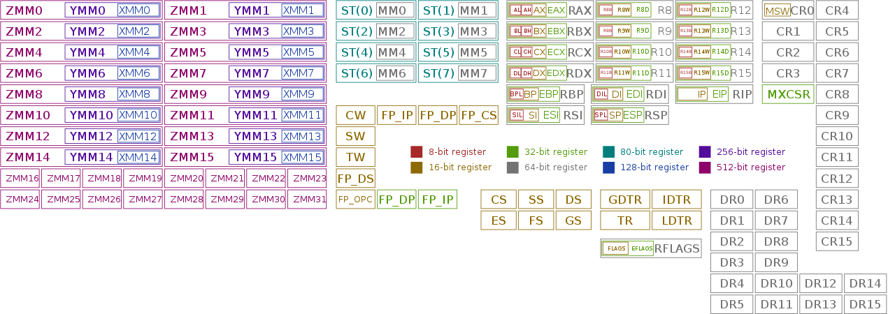
Other registers (not sure if some are specific to 64-bit processors)
- XMM0 to XMM15 are 128 bits long and nested in the YMM (256 bits) and ZMM (512 bits) registers.
- MM0 to MM7 are 64 bits long and are nested in the 80-bits FPU registers ST(0) to ST(7). (but according to x86 oddities, MM0 to MMZ actually match ST(7) to ST(0), in reverse order. Is it true?)
- These four 1-byte registers are used sometimes but not accessible directly:
- SPL: the lower byte of SP
- BPL: the lower byte of BP
- SIL: the lower byte of SI
- DIL: the lower byte of DI
Default values
All registers are initialized to 0 except:
- CX = 00FF
- SI = 0100
- DI = FFFE
- SP = FFFE
NB: In a .COM file, DX = DS = ES = SS = CS = 0000. The entry point is at CS:0100.
FLAGS is a 16-bit register containing the flags 0 to 15.
EFLAGS is a 32-bit register containing FLAGS and the flags 16 to 21 (ignored here).
RFLAGS is a 64-bit register containing EFLAGS but it is only used in 64-bit architectures.
Updating any flags also updates all the FLAGS registers and vice-versa.
+---------------+----+-----+-----+----+----+----+-----+----+-------+----+----+----+----+----+----+-----+----+-----+----+-----+----+
| Bits 63 to 22 | 21 | 20  | 19  | 18 | 17 | 16 | 15  | 14 | 12-13 | 11 | 10 | 9  | 8  | 7  | 6  | 5   | 4  | 3   | 2  | 1   | 0  |
+---------------+----+-----+-----+----+----+----+-----+----+-------+----+----+----+----+----+----+-----+----+-----+----+-----+----+
| Reserved (R)  | ID | VIP | VIF | AC | VM | RF | (R) | NT | IOPL  | OF | DF | IF | TF | SF | ZF | (R) | AF | (R) | PF | (R) | CF |
+---------------+----+-----+-----+----+----+----+-----+----+-------+----+----+----+----+----+----+-----+----+-----+----+-----+----+
Important flags
- Bit 15 is reserved and its value is 0.
- Bit 11 - Overflow Flag: is set if the result doesn't fit in the destination operand. Else, it's cleared.
- Bit 10 - Direction Flag: if it's set (by STD), the string indexes are auto-decremented from highest to lowest address. If it's cleared (by CLD), they are auto-incremented.
- Bit 9 - Interrupt Flag: if it's set (by STI or POPF), the processor can handle all interrupts. If it's cleared (by CLI or POPF) it can only handle non-maskable interrupts.
- Bit 7 - Sign Flag: is set if the most significant bit of the result is set (negative number). Else, it's cleared.
- Bit 6 - Zero Flag: is set if the result is zero. Else, it's cleared.
- Bit 5 is reserved and it's value is 0.
- Bit 4 - Adjust Flag: is set if the four less significant bits of the result generated a carry or borrow on the four upper bits. Else, it's cleared.
- Bit 3 is reserved and it's value is 0.
- Bit 2 - Parity Flag: is set if the four less significant bits of the result contain an even (= divisible by 2) number of bits set to 1. Else it's cleared.
- Bit 1 is reserved and it's value is 1.
- Bit 0 - Carry Flag: is set if the most significant bit of the result generated a carry. Else, it's cleared.
The stack is an area in the RAM used to push and pop bytes while updating the value of the stack pointer to the last value that was stored: SP (in 16-bit mode), ESP (in 32-bit mode) or RSP (in 64-bit mode).
It starts at the address FFFE (or FFFC if the program is a DOS child process), decreases at each PUSH and increases at each POP.
The top stack usually contains the value 0000h.
Segmentation is usually used to separate code, data, stack, etc. In .COM files, there's only one segment, and all the segment registers point to it.
The segment registers can be set to different values in order to read/write easily in special addresses via specific instructions:
- Write on DS with
mov. - Write on SS with
push. - Write on ES with
stosb.
(right?)
+----------------------+------------------+------------+--------+--------+-----+--------------+-----------+
| Instruction prefixes | Mandatory prefix | REX prefix | Opcode | ModR/M | SIB | Displacement | Immediate |
+----------------------+------------------+------------+--------+--------+-----+--------------+-----------+
- Instruction prefixes (1 byte each, up to 4 prefixes, optional).
- Mandatory prefix (1 byte, optional).
- REX Prefix (1 byte, optional, only for 64-bits).
- Opcode (1 to 4 bytes).
- ModR/M (1 byte, if required: 2 bits for Mod, 3 bits for Reg/Opcode, 3 bits for R/M).
- SIB (1 byte, if required: 2 bits for Scale, 3 bits for Index, 3 bits for Base).
- Displacement (1/2/4 bytes or none).
- Immediate (1/2/4 bytes or none).
The total size of an instruction is at least 1 byte (the opcode) and can't exceed 15 bytes (else, an exception is triggered).
Two prefixes of a same group can't be used together:
Lock and Repeat:
0xF0(LOCK): forces exclusive use of a shared memory in a multiprocessor environment. Can be ignored by disassemblers.0xF2(REPNE/REPNZ): repeats the instruction for each element of a string or I/O instructions, as long as the zero flag isn't set and rCX != 0.0xF3(REP/REPE/REPZ): repeats, as long as the zero flag is set and rCX == 0.0xF2can also be a bound prefix in special conditions (not clear yet).
Segment Override:
0x2E: CS is used instead of the default segment of an instruction.0x36: same, for SS.0x3E: same, for DS.0x26: same, for ES.0x64: same, for FS.0x65: same, for GS.
Exception: for JCC instructions, 0x2E prefix hints that the branch is unlikely to be taken and 0x3E hints that it's likely to be taken.
Operand-Size Override:
0x66: switching to non-default size. (on 32-bit environments, use 16-bit operands for instructions using 32-bit operands by default, and vice-versa).
Address-Size Override:
0x67: switching to non-default size. (on 32-bit environments, use 16-bit memory accesses for instructions using 32-bit addressing by default, and vice-versa).
NB: In practice, it's possible to use the same prefixes many times (uselessly) without error as long as the instruction stays below the 15-byte limit. Ex: 66 66 66 66 66 66 66 66 66 66 66 66 66 66 90: nop.
Mandatory prefixes must precede the first byte of certain opcodes.
This cancels their default behavior.
0xF2(prefix used by many instructions)0xF3(prefix used by OPCNT, LZCNT and ADOX)0x66(prefix used by some SSE instructions)
The opcode byte(s) defines the instruction itself.
- 1-byte opcodes can have any value except 0x0F or a prefix.
- 2-byte opcodes contain the escape byte 0x0F and a second opcode byte except 0x38 and 0x3A.
- 3-byte opcodes contain the escape bytes 0x0F38 or 0x0F3A and a third opcode byte.
Some opcodes contain a bit field specifying a register operand. (ex: instructions 40 to 47 (noted "40+r") perform the same operation INC on 8 different registers)
This byte is used by some instructions to determine how its operands are used.
-
Mod (2 bits) defines the addressing mode:
00: no displacement.01: 8-bit displacement.10: displacement of 16 or 32 bits, depending on the decoding mode.11: use only general-purpose registers.
-
REG (3 bits) can contain 3 extra opcode bits, or specify a (source or destination) operand register.
-
R/M (3 bits) can be combined with the Mod bits to define an addressing mode or 5 extra opcode bits, or specify an operand register.
ModR/M table
+-----------+----------------------------------------+
| REG       | 000  001  010  011  100  101  110  111 |
+-----------+----------------------------------------+
| /digit    | 0    1    2    3    4    5    6    7   |
| r8(/r)    | AL   CL   DL   BL   AH   CH   DH   BH  |
| r16(/r)   | AX   CX   DX   BX   SP   BP   SI   DI  |
| r32(/r)   | EAX  ECX  EDX  EBX  ESP  EBP  ESI  EDI |
| mm(/r)    | MM0  MM1  MM2  MM3  MM4  MM5  MM6  MM7 |
| xmm(/r)   | XMM0 XMM1 XMM2 XMM3 XMM4 XMM5 XMM6 XMM7|
| sreg      | ES   CS   SS   DS   FS   GS   res. res.|
| eee       | CR0  invd CR2  CR3  CR4  invd invd invd|
| eee       | DR0  DR1  DR2  DR3  DR41 DR51 DR6  DR7 |
+-----+-----+----------------------------------------+-------------------------+-------------------------+
| Mod | R/M | ModR/M byte (hex)                      | Effective Address (16b) | Effective Address (32b) |
+-----+-----+----------------------------------------+-------------------------+-------------------------+
| 00  | 000 | 00   08   10   18   20   28   30   38  | [BX+SI]                 | [EAX]                   |
|     | 001 | 01   09   11   19   21   29   31   39  | [BX+DI]                 | [ECX]                   |
|     | 010 | 02   0A   12   1A   22   2A   32   3A  | [BP+SI]                 | [EDX]                   |
|     | 011 | 03   0B   13   1B   23   2B   33   3B  | [BP+DI]                 | [EBX]                   |
|     | 100 | 04   0C   14   1C   24   2C   34   3C  | [SI]                    | [sib]                   |
|     | 101 | 05   0D   15   1D   25   2D   35   3D  | [DI]                    | [EIP]+disp32            |
|     | 110 | 06   0E   16   1E   26   2E   36   3E  | disp16                  | [ESI]                   |
|     | 111 | 07   0F   17   1F   27   2F   37   3F  | [BX]                    | [EDI]                   |
+-----+-----+----------------------------------------+-------------------------+-------------------------+
| 01  | 000 | 40   48   50   58   60   68   70   78  | [BX+SI]+disp8           | [EAX]+disp8             |
|     | 001 | 41   49   51   59   61   69   71   79  | [BX+DI]+disp8           | [EDX]+disp8             |
|     | 010 | 42   4A   52   5A   62   6A   72   7A  | [BP+SI]+disp8           | [EDX]+disp8             |
|     | 011 | 43   4B   53   5B   63   6B   73   7B  | [BP+DI]+disp8           | [EBX]+disp8             |
|     | 100 | 44   4C   54   5C   64   6C   74   7C  | [SI]+disp8              | [sib]+disp8             |
|     | 101 | 45   4D   55   5D   65   6D   75   7D  | [DI]+disp8              | [EBP]+disp8             |
|     | 110 | 46   4E   56   5E   66   6E   76   7E  | [BP]+disp8              | [ESI]+disp8             |
|     | 111 | 47   4F   57   5F   67   6F   77   7F  | [BX]+disp8              | [EDI]+disp8             |
+-----+-----+----------------------------------------+-------------------------+-------------------------+
| 10  | 000 | 80   88   90   98   A0   A8   B0   B8  | [BX+SI]+disp16          | [EAX]+disp32            |
|     | 001 | 81   89   91   99   A1   A9   B1   B9  | [BX+DI]+disp16          | [ECX]+disp32            |
|     | 010 | 82   8A   92   9A   A2   AA   B2   BA  | [BP+SI]+disp16          | [EDX]+disp32            |
|     | 011 | 83   8B   93   9B   A3   AB   B3   BB  | [BP+DI]+disp16          | [EBX]+disp32            |
|     | 100 | 84   8C   94   9C   A4   AC   B4   BC  | [SI]+disp16             | [sib]+disp32            |
|     | 101 | 85   8D   95   9D   A5   AD   B5   BD  | [DI]+disp16             | [EBP]+disp32            |
|     | 110 | 86   8E   96   9E   A6   AE   B6   BE  | [BP]+disp16             | [ESI]+disp32            |
|     | 111 | 87   8F   97   9F   A7   AF   B7   BF  | [BX]+disp16             | [EDI]+disp32            |
+-----+-----+----------------------------------------+-------------------------+-------------------------+
| 11  | 000 | C0   C8   D0   D8   E0   E8   F0   F8  | AL/AX/EAX/ST0/MM0/XMM0  | AL/AX/EAX/ST0/MM0/XMM0  |
|     | 001 | C1   C9   D1   D9   E1   E9   F1   F9  | CL/CX/ECX/ST1/MM1/XMM1  | CL/CX/ECX/ST1/MM1/XMM1  |
|     | 010 | C2   CA   D2   DA   E2   EA   F2   FA  | DL/DX/EDX/ST2/MM2/XMM2  | DL/DX/EDX/ST2/MM2/XMM2  |
|     | 011 | C3   CB   D3   DB   E3   EB   F3   FB  | BL/BX/EBX/ST3/MM3/XMM3  | BL/BX/EBX/ST3/MM3/XMM3  |
|     | 100 | C4   CC   D4   DC   E4   EC   F4   FC  | AH/SP/ESP/ST4/MM4/XMM4  | AH/SP/ESP/ST4/MM4/XMM4  |
|     | 101 | C5   CD   D5   DD   E5   ED   F5   FD  | CH/BP/EBP/ST5/MM5/XMM5  | CH/BP/EBP/ST5/MM5/XMM5  |
|     | 110 | C6   CE   D6   DE   E6   EE   F6   FE  | DH/SI/ESI/ST6/MM6/XMM6  | DH/SI/ESI/ST6/MM6/XMM6  |
|     | 111 | C7   CF   D7   DF   E7   EF   F7   FF  | BH/DI/EDI/ST7/MM7/XMM7  | BH/DI/EDI/ST7/MM7/XMM7  |
+-----+-----+----------------------------------------+-------------------------+-------------------------+
SIB is not used in 16-bit environments. It allows to use an absolute address as one of the ModR/M fields.
This byte is read in only two cases, just after the ModR/M byte:
- If one of the ModR/M fields refers to the ESP register.
- If Mod == 00 and R/M == 5 (EBP). In this case, EBP is not used, and the SIB byte is used instead.
(This means that the only way to use EBP as-is via ModR/M is to have Mod = 01 + 8-bit displacement = 0).
It contains:
- 2 bits for Scale
- 3 bits for Index, representing any register except ESP
- 3 bits for Base
and targets the address [Index * 2 ^ Scale + Base].
SIB table
+----------------------+-----------------------------------------------+
| Base                 | 000   001   010   011   100   101   110   111 |
| decimal              | 0     1     2     3     4     5     6     7   |
| r32                  | EAX   ECX   EDX   EBX   ESP   *     ESI   EDI |
+---------+----+-------+-----------------------------------------------+
| SIB     | SS | Index | SIB Byte (hex)                                |
+---------+----+-------+-----------------------------------------------+
| [EAX]   | 00 | 000   | 00    01    02    03    04    05    06    07  |
| [ECX]   |    | 001   | 08    09    0A    0B    0C    0D    0E    0F  |
| [EDX]   |    | 010   | 10    11    12    13    14    15    16    17  |
| [EBX]   |    | 011   | 18    19    1A    1B    1C    1D    1E    1F  |
| none    |    | 100   | 20    21    22    23    24    25    26    27  |
| [EBP]   |    | 101   | 28    29    2A    2B    2C    2D    2E    2F  |
| [ESI]   |    | 110   | 30    31    32    33    34    35    36    37  |
| [EDI]   |    | 111   | 38    39    3A    3B    3C    3D    3E    3F  |
+---------+----+-------+-----------------------------------------------+
| [EAX*2] | 01 | 000   | 40    41    42    43    44    45    46    47  |
| [ECX*2] |    | 001   | 48    49    4A    4B    4C    4D    4E    4F  |
| [EDX*2] |    | 010   | 50    51    52    53    54    55    56    57  |
| [EBX*2] |    | 011   | 58    59    5A    5B    5C    5D    5E    5F  |
| none    |    | 100   | 60    61    62    63    64    65    66    67  |
| [EBP*2] |    | 101   | 68    69    6A    6B    6C    6D    6E    6F  |
| [ESI*2] |    | 110   | 70    71    72    73    74    75    76    77  |
| [EDI*2] |    | 111   | 78    79    7A    7B    7C    7D    7E    7F  |
+---------+----+-------+-----------------------------------------------+
| [EAX*4] | 10 | 000   | 80    81    82    83    84    85    86    87  |
| [ECX*4] |    | 001   | 88    89    8A    8B    8C    8D    8E    8F  |
| [EDX*4] |    | 010   | 90    91    92    93    94    95    96    97  |
| [EBX*4] |    | 011   | 98    99    9A    9B    9C    9D    9E    9F  |
| none    |    | 100   | A0    A1    A2    A3    A4    A5    A6    A7  |
| [EBP*4] |    | 101   | A8    A9    AA    AB    AC    AD    AE    AF  |
| [ESI*4] |    | 110   | B0    B1    B2    B3    B4    B5    B6    B7  |
| [EDI*4] |    | 111   | B8    B9    BA    BB    BC    BD    BE    BF  |
+---------+----+-------+-----------------------------------------------+
| [EAX*8] | 11 | 000   | C0    C1    C2    C3    C4    C5    C6    C7  |
| [ECX*8] |    | 001   | C8    C9    CA    CB    CC    CD    CE    CF  |
| [EDX*8] |    | 010   | D0    D1    D2    D3    D4    D5    D6    D7  |
| [EBX*8] |    | 011   | D8    D9    DA    DB    DC    DD    DE    DF  |
| none    |    | 100   | E0    E1    E2    E3    E4    E5    E6    E7  |
| [EBP*8] |    | 101   | E8    E9    EA    EB    EC    ED    EE    EF  |
| [ESI*8] |    | 110   | F0    F1    F2    F3    F4    F5    F6    F7  |
| [EDI*8] |    | 111   | F8    F9    FA    FB    FC    FD    FE    FF  |
+---------+----+-------+-----------------------------------------------+
(*) If base == 5, its value depends on the Mod bits of the ModR/M byte:
- 00: base = disp32
- 01: base = EBP + disp8
- 10: base = EBP + disp32
Displacement (optional) is encoded on 1, 2 or 4 bytes according to the Mod and R/M bits, and must follow the ModR/M or the SIB byte.
A signed number (optional), directly encoded on 1, 2 or 4 bytes, according to the decoding mode and prefixes. It must be at the end of the instruction.
The full instruction set is summarized in instructions.md.
Mnemonic collision
movsd refers to two opcodes:
A5: "Move Data from String to String"F2: "Move Scalar Double-precision floating-point"
- Install NASM and DosBox.
- Compile .asm file in .COM with
nasm xxx.asm -fbin -o xxx.com - Disassemble a .COM file and show it in the terminal with
ndisasm -o100h xxx.com(16-bit mode by default. Add-b 32after ndiasm for 32-bit programs) - View a .COM file size with
dir xxx.com - Test a .COM file by running it wirh DosBox (drag & drop the file on the DosBox shortcut, adjust speed with ctrl+F11 & ctrl+F12)
Algorithm:
- Check if the current byte is an instruction prefix byte (F3, F2, or F0). if so, you've got a REP/REPE/REPNE/LOCK prefix. Advance to the next byte.
- Check to see if the current byte is an address size byte (67). If so, decode addresses in the rest of the instruction in 16-bit mode if currently in 32-bit mode, or in 32-bit mode if currently in 16-bit mode.
- Check to see if the current byte is an operand size byte (66). If so, decode immediate operands in 16-bit mode if currently in 32-bit mode, or in 32-bit mode if currently in 16-bit mode.
- Check to see if the current byte is a segment override byte (2E, 36, 3E, 26, 64, or 65). If so, use the corresponding segment register for decoding addresses instead of the default segment register.
- The next byte is the opcode. If the opcode is 0F, then it is an extended opcode, and read the next byte as the extended opcode.
- Depending on the particular opcode, read in and decode a Mod R/M byte, a Scale Index Base (SIB) byte, a displacement (0, 1, 2, or 4 bytes), and/or an immediate value (0, 1, 2, or 4 bytes). The sizes of these fields depend on the opcode , address size override, and operand size overrides previously decoded.
(for x86, steps 1 to 4 can be in any order and repeated. For x86-64 and modern instruction sets like AVX / AVX2, it's strictly in this order)
Notes:
- When it encounters data bytes in the .COM file, the disassembler can try to interpret them as instructions. To avoid that, the disassembler can try to determine (like an emulator) which addresses the instruction pointer can really reach via normal execution, jumps or interrupts. Else, some sort of manual separation of code and data would be necessary to be totally accurate.
- The bytes that don't belong to any instruction can be disassembled as
dbstatements. Their type (number, string, ...) depends on the instructions using them, so it would be wise to provide numeric and string values for each byte of data. - In .COM demos, data bytes are generally placed at the end of the program. The beginning is used by instructions stored sequentially and end with
ret. (lazy devs may rely only on that to stop reading instructions)
A x86 emulator needs to reproduce the behavior of all (nested) registers, flags, memory, disassemble and execute every instruction, and handle input (mouse, keyboard), output (screen, sound) and interrupts.
The current project (minix86) is an example of how to do so in JavaScript.
Software iterrupts are triggered by the INT x instruction. According to the value of x (between 0h and FFh), a predefined program is executed.
If x equals 0x20 to 0x2F, a MS-DOS API call is performed. The value of AH indicated the subprogram to run.
The most important interrupts are:
INT 10h && AH = 00h: Set video mode according to the value ofAL. (generally13h)INT 16h && AH = 1: Read keystroke (AL is set to the value of the ASCII char)INT 21h && AH = 09h: Display a string ($-terminated string, address stored in DX, automatic line break after the 80th column)- ...
Textmode (default, Mode 3)
- 80x25 chars
- Chars are drawn in 8*16px boxes.
- Screen resolution: 640*400px
- 16 colors (palette)
- 2 bytes per char (8 bits for char, 4 bits for text color, 4 bits for background color)
- Starts at address video memory starts at 0xB800:0000
- Charset: Code Page 437. (256 characters)
NB: char size, resolution and color palette vary with the hardware used. These seem to be the most common ones.
Example:
org 100h			    ; we start at CS:100h
xchg 	bp,ax		    ; put 09h into AH
mov		dx,text		    ; DX expects the adress of a $ terminated string
int 	21h			    ; call the DOS function (AH = 09h)
ret					    ; quit
text: db 'Hello World!$'
This page shows how to output text via low-level access:
Mode 13h
- 320x200
- 256 colors (Default palette)
- The palette can be modified with code
- 1 byte per pixel (color)
- Starts at address A000:0000
Example:
Init:
mov al,0x13
int 0x10
Set ES to A000:0000 (or another segent register):
push 0xa000
pop es
Draw a pixel on screen:
- Write on ES with
stosb. - Write on DS with
mov. - Write on SS with
push.
Other video modes
Many exist but very few are used in demoscene, besides text and 13h.
ESC key:
in      al,60h          ;read whatever is at keyboard port; looking for ESC which is #1
dec     ax              ;if ESC, AX now 0
jnz     mainloop        ;fall through if 0, do jump somewhere else if otherwise
Any key:
The most reliable way is to use an interrupt (INT 16h / AH=1):
mov ah,1           ; subfunction AH = 1, check for key
int 16h
jz  mainloop       ; ZF set if no keystroke available
- Show mouse cursor with:
INT 33h / AX=0001h - Get position and button status with
INT 33h / AX=0003h(CX = row, DX = column, BX bits 0/1/2 = left/center/right button down) - etc...
MIDI audio output can be produced by writing on the MIDI control port (0x331) and MIDI data port (0x330).
Here are all the sources used to write this guide:
- Intel's x86 and 64 manuals (especially vol. 2)
- x86 opcode and instruction reference by MazeGen (especially coder32)
- Sandpile
- x86 Opcode Structure and Instruction Overview
- Mode 13h and default color palette
- x86/x64 Machine Code
- Tiny x86 prods wiki
- How to write a disassembler
- Intel vs AT&T syntax
- Table of x86 registers
- FLAGS register
- A Magnetized Needle and a Steady Hand
- x86 oddities + Corkami Standard Test + download
- x86 disassembly
- x86 on wikipedia
- CP437
- MS-DOS API
- Interrupts
- x86 disassembler & emulator in JS, coming soon in this repo