-
Notifications
You must be signed in to change notification settings - Fork 335
Part 3: shadertoy
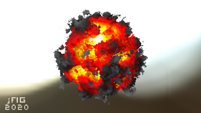
Now let us program a real GPU. Here is an example, how is it made?
So far I have told a lot about the general principles of computer graphics, but all the examples were made in bare C++. This time we will try GLSL. The general principle of raytracing is extremely simple. We take a camera, then we define a grid of pixels (our screen) in front of the camer, we emit a ray through each pixel, and we see where exactly it intersects with our scene. Here's an illustration:
And here is the main part of the raytracing done on a CPU: we simply loop through all the pixels and write the color into the framebuffer. Please note the #pragma omp parallel for! All the computations are independent one from another.
    vec3 origin = [...];
    #pragma omp parallel for
    for (size_t j = 0; j<height; j++) {
        for (size_t i = 0; i<width; i++) {
            vec3 direction = [...];
            framebuffer[i+j*width] = cast_ray(origin, direction);
        }
}Let us see how to do it on a GPU. The task is to fill an image with a color gradient, the idea is to be sure that we can control the output on the screen. Here is the result:

And here is the complete code that displays this image. You can see and execute this code here.
void mainImage( out vec4 fragColor, in vec2 fragCoord ) {
    vec2 uv = fragCoord/iResolution.xy;
    vec3 col = vec3(uv.x, uv.y, 0.);
    fragColor = vec4(col, 1.);
}
The main difference with the CPU code is that there is no double loop over all pixels of the picture, this is what the GPU does for us. The mainImage function is called for each pixel of the picture, it gets the coordinates of the fragCoord pixel at the input and the function must return its color fragColor. It's simple, isn't it? Check what experts can do with this approach:
This code is called a fragment shader.
Now I want to write the conference title on top of the image, it should look like this:

The source code is available at shadertoy.
The main idea is simple. Imagine that we have a 2d array of boolean values bool jfig[32][18]. Let us split our image into a grid of 32x18 squares, and lighten those corresponding to true valies in the array jfig:
void mainImage( out vec4 fragColor, in vec2 fragCoord ) {
    vec2 uv = fragCoord/iResolution.xy;
    vec3 col = vec3(uv.x, uv.y, 0.);

    vec2 coord = fragCoord/iResolution.xy*vec2(32, 18);
    if (jfig(uint(coord.x), uint(coord.y))) {
        col += vec3(.5);
    }

    fragColor = vec4(col, 1.);
}
Of course, I do not want to store 32*18 booleans, because bool in GLSL takes.... 32 bits! Therefore I store this binary image in a bitfield jfig_bitfield and the wrapper bool jfig(in uint x, in uint y) extracts the bit we want:
#define JFIGW 32u
#define JFIGH 18u
uint[] jfig_bitfield = uint[]( 0x0u,0x0u,0x0u,0xf97800u,0x90900u,0xc91800u,0x890900u,0xf90900u,0x180u,0x0u,0x30e30e0u,0x4904900u,0x49e49e0u,0x4824820u,0x31e31e0u,0x0u,0x0u,0x0u );
bool jfig(in uint x, in uint y) {
    uint id = x + (JFIGH-1u-y)*JFIGW;
    if (id>=JFIGW*JFIGH) return false;
    return 0u != (jfig_bitfield[id/32u] & (1u << (id&31u)));
}At this step we should obtain this image:

You can see and execute the source code at shadertoy. This step is crucial, because the main raytracing job is done here. The background image we use is not a flat one, but a cube mapping texture.
Here is the source code:
struct Ray {
    vec3 origin;
    vec3 dir;
};

vec3 cast_ray(in Ray ray) {
	return texture(iChannel0, ray.dir).xyz;
}

void mainImage( out vec4 fragColor, in vec2 fragCoord ) {
    const float fov = 3.1416 / 4.;
    vec2 uv = (fragCoord/iResolution.xy*2. - 1.)*tan(fov/2.);
    uv.x *= iResolution.x/iResolution.y;
    vec3 orig = vec3(0., 0., 1.);
    vec3 dir = normalize(vec3(uv, -1));

    vec3 col = cast_ray(Ray(orig, dir));

    fragColor = vec4(col, 1.);
}
The most difficult part in this code is the first 5 lines after the declaration of the function mainImage. What is happening there? Let us suppose that the camera is placed in the origin and is directed along the -z axis. Here is an illustration, it shows the camera from the top, the y axis points towards you out of the screen:

The virtual screen lies at the plane with equation z=-1. The field of view (constant) defines a sector that will be visible on our rendering. In this illustration my screen is 16 pixels wide, let us calculate its length in world units. Let us consider the triangle dfined by the red, gray and dashed grey lines. It is easy to see that tan(fov/2) = (screen width) * 0.5 / (screen - camera distance). We have put the screen at 1 meter distance from the camera, therefore (screen width) = 2 * tan (fov/2).
Now let us imagine that we want to emit a ray trough the 12th pixel of the screen, i.e. we want to calculate the coordinates of the blue vector. What is the distance from the left side of the screen to the tip of the vector? First of all, it is 12+0.5 pixels. We know that 16 pixels of the screen correspond to 2*tan(fov/2) meters. So, the tip of the blue vector is situated (12+0.5)/16 * 2*tan(fov/2) meters from the left side of the screen, or (12+0.5) * 2/16 * tan(fov/2) - tan(fov/2) meters from the intersection of the screen with the axis -z. Add to this computation the screen aspect ratio and you will get the above five lines of code. Well, in the code the camera is situated at the point (0,0,1) and the screen lies in the plane z=0, but it does not change our computations.
As before, you can see and execute the source code here. I want to obtain this result:
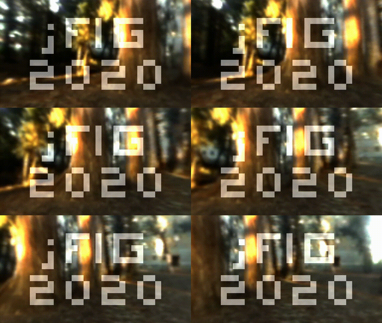
In the previous step our camera was situated in the point (0,0,1) and was directed along the axis -z, and now I want it to fly in circles, looking to the origin. Seven lines of code give the desired effect:
vec3 rotateCamera(in vec3 orig, in vec3 dir, in vec3 target) {
    vec3 zAxis = normalize(orig - target);
    vec3 xAxis = normalize(cross(vec3(0., 1., 0.), zAxis));
    vec3 yAxis = normalize(cross(zAxis, xAxis));
    mat4 transform = mat4(vec4(xAxis, 0.), vec4(yAxis, 0.), vec4(zAxis, 0.), vec4(orig, 1.));
    return (transform * vec4(dir, 0.)).xyz;
}

void mainImage( out vec4 fragColor, in vec2 fragCoord ) {
[...]
    vec3 orig = vec3(-sin(iTime/4.), 0., cos(iTime/4.));
    vec3 dir = normalize(vec3(uv, -1));
    dir = rotateCamera(orig, dir, vec3(0.));
[...]
}Let us draw a square with 0.5 meters edge living in the plane z=0:
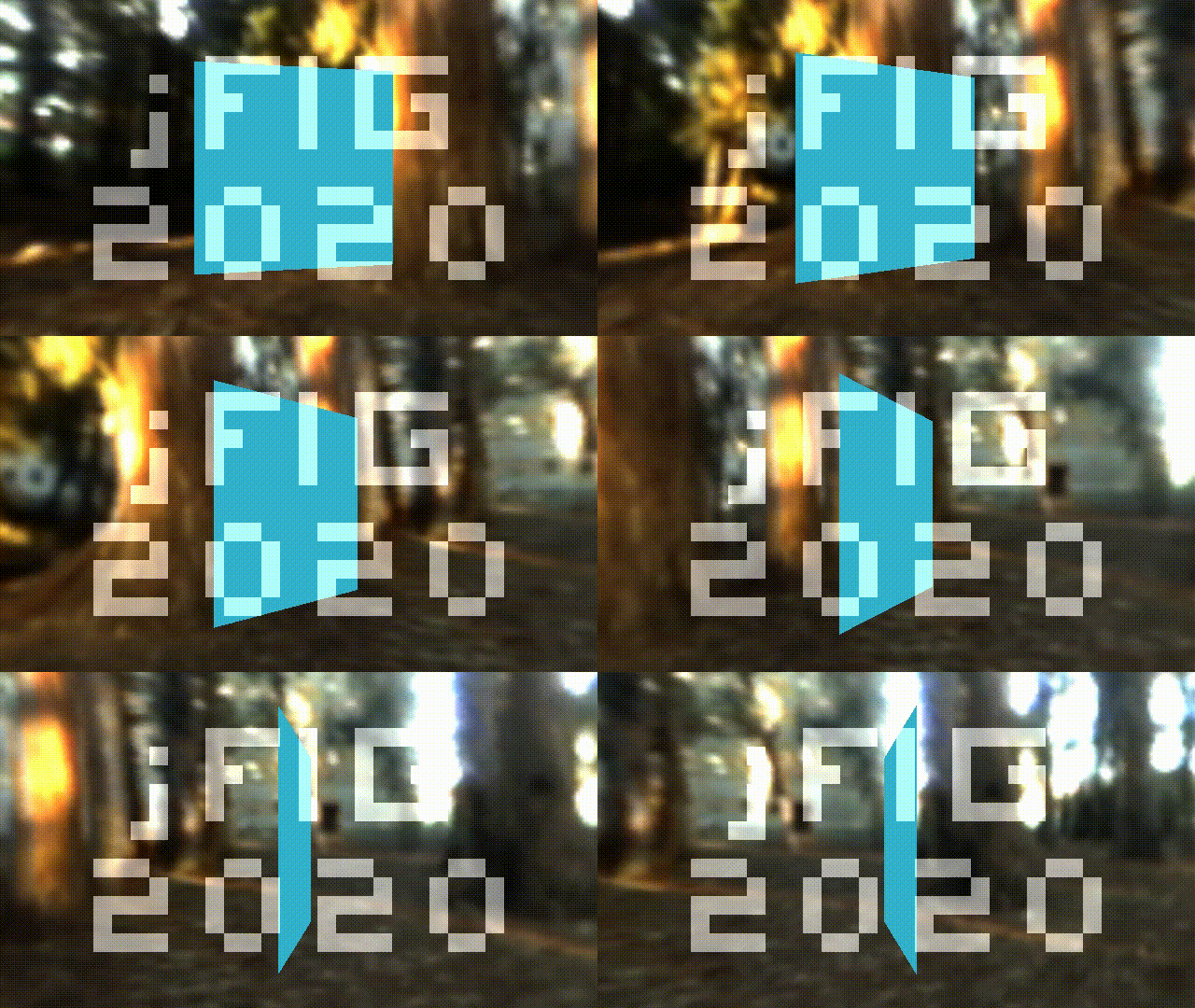
To achieve this, it suffices to add few lines into the function cast_ray():
vec3 cast_ray(in Ray ray) {
    if (abs(ray.dir.z)>1e-5) {
        float dist = (0. - ray.origin.z) / ray.dir.z;
        if (dist > 0.) {
	        vec3 point = ray.origin + ray.dir*dist;
        	if (point.x>-.25 && point.x<.25 && point.y>-.25 && point.y<.25) {
                      return vec3(0.2, 0.7, 0.8);
        	}
          }
    }
   return texture(iChannel0, ray.dir).xyz;
}
Check the source code at shadertoy.
How does it work? We need to find the intersection of a ray and the plane of the square (z=0). First I check if the the ray is parallel to the plane if (abs(ray.dir.z)>1e-5). The equation of the ray can be expressed as vec3 point = ray.origin + dist*ray.dir, where dist - is the distance from the origin of the ray to the current point, right? We know the z coordinate of the intersection (z=0); then the distance from the ray origin to the intersection point can be found as float dist = (0. - ray.origin.z) / ray.dir.z. The hardest part is done: having computed the intersection point we check whether x and y coordinates are inside a square with .5 meters edge. Voilà!
Well, if we know how to draw one square, we could try to draw six! Check the source code here.
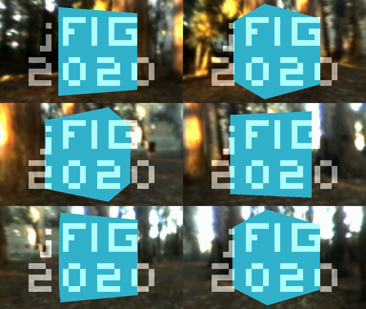
Here is a function that computes the intersection of an arbitrary ray with a cube aligned with the coordinate axes:
struct Box {
    vec3 center;
    vec3 halfsize;
};

bool box_ray_intersect(in Box box, in Ray ray, out vec3 point, out vec3 normal) {
	for (int d=0; d<3; d++) {
    	if (abs(ray.dir[d])<1e-5) continue;
		float side = (ray.dir[d] > 0. ? -1.0 : 1.0);
        float dist = (box.center[d] + side*box.halfsize[d] - ray.origin[d]) / ray.dir[d];
		if (dist < 0.) continue;
        point = ray.origin + ray.dir*dist;
        int i1 = (d+1)%3;
        int i2 = (d+2)%3;
        if (point[i1]>box.center[i1]-box.halfsize[i1] && point[i1]<box.center[i1]+box.halfsize[i1] &&
        	point[i2]>box.center[i2]-box.halfsize[i2] && point[i2]<box.center[i2]+box.halfsize[i2]) {
            normal = vec3(0);
            normal[d] = side;
            return true;
        }
	}
    return false;
}Let us add flat shading to our rendering:
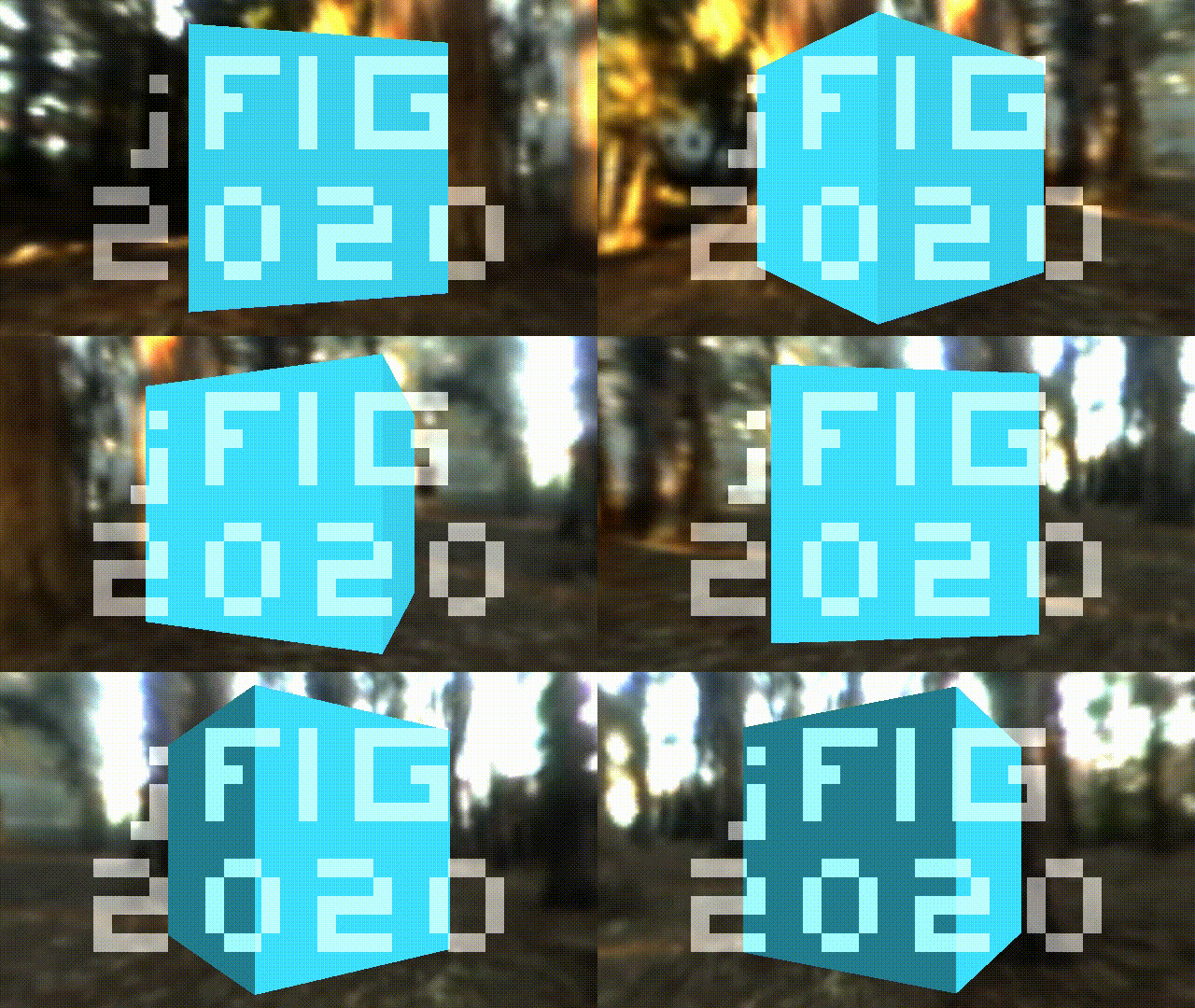
As before, the source code is available at shadertoy. Here is our shading routine:
struct Light {
    vec3 position;
    vec3 color;
};

Light[] lights = Light[]( Light(vec3(-15,10,10), vec3(1,1,1)) );

vec3 cast_ray(in Ray ray) {
    vec3 p, n;
    if (box_ray_intersect(Box(vec3(0.), vec3(.25)), ray, p, n)) {
	   	vec3 diffuse_light = vec3(0.);
    	for (int i=0; i<lights.length(); i++) {
       		vec3 light_dir = normalize(lights[i].position - p);
	       	diffuse_light  += lights[i].color * max(0., dot(light_dir, n));
        }
       	return vec3(0.2, 0.7, 0.8)*(vec3(.7,.7,.7) + diffuse_light);
    }
	return texture(iChannel0, ray.dir).xyz;
}Since we know to draw one cube, we can draw several:

Check the shadertoy code. Like with the conference name (2d binary image), I define the bunny as a 3d array of boolean values packed into a bitfield:
#define BUNW 6
#define BUNH 6
#define BUND 4
#define BUNVOXSIZE 0.1
uint[] bunny_bitfield = uint[]( 0xc30d0418u, 0x37dff3e0u, 0x7df71e0cu, 0x004183c3u, 0x00000400u );
bool bunny(in int cubeID) {
    if (cubeID<0 || cubeID>=BUNW*BUNH*BUND) return false;
    return 0u != (bunny_bitfield[cubeID/32] & (1u << (cubeID&31)));
}
If you do not understand the constants like 0xc30d0418u, here how they look in a human-readable format :)

Here is a function that computes the intersection of an arbitrary ray and the voxelized bunny:
bool bunny_ray_intersect(in Ray ray, out vec3 point, out vec3 normal) {
    float bunny_dist = 1e10;
    for (int i=0; i<BUNW; i++) {
    	for (int j=0; j<BUNH; j++) {
    		for (int k=0; k<BUND; k++) {
                int cellID = i+j*BUNW+k*BUNW*BUNH;
				if (!bunny(cellID)) continue;
                Box box = Box(vec3(i-BUNW/2,j-BUNH/2,-k+BUND/2)*BUNVOXSIZE+vec3(.5,.5,-.5)*BUNVOXSIZE, vec3(1.,1.,1.)*BUNVOXSIZE*.45);
                vec3 p, n;
                if (box_ray_intersect(box, ray, p, n) && length(p-ray.origin) < bunny_dist) {
                    bunny_dist = length(p-ray.origin);
                    point = p;
                    normal = n;
                }
    		}
    	}
    }
	return bunny_dist < 1e3;
}
And if we replace box_ray_intersect() call with bunny_ray_intersect() inside the cast_ray() function, we can see the bunny!
The very last thing is to color the cubes. Check shadertoy for the source code.

I did not whant to reinvent the wheel, and copy-pasted someone else's code that gives a color for every integer value (cube id):
# That's all, folks! Shadertoy.com is full of very interesting shaders, but it can be hard to understand how they are built. If you are interested, you can try to understand how works [tinykaboom!](https://github.com/ssloy/tinykaboom/wiki):

